IS0 12870 Ophthalmic optics-Spectacle frames Requirements and Test Methods
IS0 12870
Ophthalmic optics-Spectacle frames Requirements and test methods
Fifth edition2024-11
Optique ophtalmique - Montures de lunettes - Exigences etméthodes d'essai
Content
• Foreword
• 1 Scope
• 2 Normative references
• 3 Terms and definitions
• 3.1 General terms
• 3.2 Types of frame
• 3.3 Terms describing frame materials
• 4 Requirements
• 4.1 General
• 4.2 Construction
• 4.3 Risk management
• 4.4 Biological compatibility
• 4.5 Nickel release (optional)
• 4.6 Clinical evaluation
• 4.7 Measurement system
• 4.8 Dimensional tolerances on nominal size
• 4.9 Tolerance on screw threads (optional)
• 4.10 Dimensional stability at elevated temperature
• 4.11 Resistance to perspiration
• 4.12 Mechanical stability
• 4.12.1 Bridge deformation
• 4.12.2 Lens retention characteristics
• 4.12.3 Endurance
• 4.13 Resistance to ignition
• 4.14 Resistance to optical radiation (optional)
• 5 Selection of test samples
• 5.1 General
• 5.2 Testing for nickel release
• 5.3 Change in spectacle frame model
• 6 Preparation and conditioning of test samples
• 6.1 Test lenses
• 6.2 Sample conditioning and test conditions
• 7 Testing, inspection and conformity
• 7.1 Testing
• 7.2 Inspection and examination
• 7.3 Conformity
• 8 Test methods
• 8.1 General
• 8.2 Test for dimensional stability
• 8.2.1 Apparatus
• 8.2.2 Procedure
• 8.3 Test for resistance to perspiration
• 8.3.1 Apparatus and reagents
• 8.3.2 Procedure
• 8.4 Bridge deformation and lens retention
• 8.4.1 Apparatus
• 8.4.2 Procedure
• 8.5 Endurance test
• 8.5.1 Apparatus
• 8.5.2 Procedure
• 8.6 Test for resistance to ignition
• 8.6.1 Apparatus
• 8.6.2 Procedure
• 8.7 Test for resistance to optical radiation (optional)
• 8.7.1 Apparatus
• 8.7.2 Procedure
• 9 Marking
• 10 Additional information to be supplied by the manufacturer or other person placing the product on the market
• 11 Reference to this document
• Annex A (informative) Recommendations for the use of spectacle frames
• Annex B (informative) Chemicals that can be harmful to health
• Annex C (informative) European requirements legislation on nickel release
• Annex D (informative) Examples of layout of test equipment
• Annex E (normative) Long wavelength pass
• Annex F (informative) Identification marking or labelling of handling requirements (optional)
• Bibliography
Foreword
ISO (the International Organization for Standardization) is a worldwide federation of national standards bodies (ISO member bodies). The work of preparing International Standards is normally carried out through ISO technical committees. Each member body interested in a subject for which a technical committee has been established has the right to be represented on that committee. International organizations, governmental and non-governmental, in liaison with ISO, also take part in the work. ISO collaborates closely with the International Electrotechnical Commission (IEC) on all matters of electrotechnical standardization.
The procedures used to develop this document and those intended for its further maintenance are described in the ISO/IEC Directives, Part 1. In particular, the different approval criteria needed for the different types of ISO documents should be noted. This document was drafted in accordance with the editorial rules of the ISO/IEC Directives, Part 2 (see www.iso.org/directives).
Attention is drawn to the possibility that some of the elements of this document may be the subject of patent rights. ISO shall not be held responsible for identifying any or all such patent rights. Details of any patent rights identified during the development of the document will be in the Introduction and/or on the ISO list of patent declarations received (see www.iso.org/patents).
Any trade name used in this document is information given for the convenience of users and does not constitute an endorsement.
For an explanation on the voluntary nature of standards, the meaning of ISO specific terms and expressions related to conformity assessment, as well as information about ISO's adherence to the World Trade Organization (WTO) principles in the Technical Barriers to Trade (TBT), see the following URL: www.iso.org/iso/foreword.html
This document was prepared by Technical Committee ISO/TC 172, Optics and photonics, Subcommittee SC 7, Ophthalmic optics and instruments, in collaboration with the European Committee for Standardization (CEN) Technical Committee CEN/TC 170, Ophthalmic optics, in accordance with the Agreement on technical cooperation between ISO and CEN (Vienna Agreement).
This fifth edition cancels and replaces the fourth edition (ISO 12870:2016), which has been technically revised.
The main changes are as follows:
Rimmed clip-ons, prescription inserts, and frames made by additive manufacture are now included in the scope
Additional terms and definitions
Clarification of the tests to be applied for the biological properties of custom-made frames in Table 1 (in 4.1)
Some re-arrangement of and additional text in 4.2
Simplification of the text in 4.2 to make it more general, and addition of a note on magnets
Additional wording has been added to 4.12.3 and 8.5 to emphasize that the apparatus prevents rotational movements of the "fixed" side
Minor changes to 4.2.6.1, 8.5.2.3, 8.6, 8.7 (with a new Annex E), Clause 9 and 10.3
Clauses 4.5 and 4.9 have been made optional, while the original 10.5 and 10.6 are now included as a note to 4.2
Clause 10.1 refers to an informative Annex F on frame handling information
Any feedback or questions on this document should be directed to the user's national standards body. A complete listing of these bodies can be found at: www.iso.org/members.html
Ophthalmic Optics — Spectacle Frames — Requirements and Test Methods
1 Scope
This document specifies fundamental requirements and their test methods for unglazed spectacle frames designed for use with prescription lenses. It is applicable to spectacle frames at the point of sale by the manufacturer or supplier to the retailer.
This document is applicable to:
All mass-produced spectacle frame types, including rimless mounts, semi-rimless mounts, and folding spectacle frames
Spectacle frames made from natural organic materials
The frame or mount of clip-ons designed specifically for attachment to particular models of spectacle frame, but not to their lenses or filters to which ISO 16034 or ISO 12312-1 apply
Prescription inserts designed for attachment to particular models of, for example, eye protectors, sunglasses, or diving masks
Parts of this document are applicable to custom-made frames — see Clause 3.1.3 and Table 1.
NOTE: See Annex A for recommendations on the design of spectacle frames and terms to be used when describing metal frames.
This document is not applicable to:
Spectacle frames used in eye protection where ISO 16321-1 applies
Sunglasses with afocal filters where ISO 12312-1 applies
2 Normative References
The following documents are referred to in the text in such a way that some or all of their content constitutes requirements of this document.
For dated references, only the edition cited applies.
For undated references, the latest edition of the referenced document (including any amendments) applies.
Referenced standards:
ISO 105-A02 — Textiles — Tests for colour fastness — Part A02: Grey scale for assessing change in colour
ISO 3696 — Water for analytical laboratory use — Specification and test methods
ISO 7998 — Ophthalmic optics — Spectacle frames — Lists of equivalent terms and vocabulary
ISO 8624 — Ophthalmic optics — Spectacle frames — Measuring system and vocabulary
ISO 11380 — Optics and optical instruments — Ophthalmic optics — Formers
ISO 11381 — Ophthalmic optics — Spectacle frames — Screw threads
EN 16128 — Ophthalmic optics — Reference method for the testing of spectacle frames and sunglasses for Nickel release
3 Terms and Definitions
For the purposes of this document, the terms and definitions given in ISO 7998 and ISO 8624, as well as the following, apply.
ISO and IEC maintain terminology databases for use in standardization at the following addresses:
ISO Online Browsing Platform: https://www.iso.org/obp
IEC Electropedia: https://www.electropedia.org
3.1 General Terms
3.1.1 Spectacle Frame Model
Spectacle frame produced to a common design, using the same materials but not necessarily the same pigmentation and surface treatment.
3.1.2 Mass-Produced Frame
Frame that is based on standardized dimensions/designs and is typically produced in a continuous production run or homogeneous batch.
Note 1 to entry: A homogeneous batch will be made to the same specifications using the same machine/equipment set-up.
Note 2 to entry: A mass-produced frame is not designed for a particular individual but may have to be adapted to fit the wearer's facial features during dispensing and will be adapted by fitting it with spectacle lenses. [SOURCE: Adapted from IMDRF N49:2018, 4.7 and 4.8]
3.1.3 Custom-Made Frame
Frame made to a written request from a person authorized by national law for the sole use of a particular individual, to address the specific anatomo-physiological features, pathological condition, or frame colour or design request of the individual for whom it is intended.
Note 1 to entry: Frames that are patient-matched, adaptable, or mass-produced shall not be considered to be custom-made.
Note 2 to entry: A custom-made frame is intended for a case where an individual’s specific needs cannot be met, or cannot be met at the appropriate level of performance, by an alternative device available on the market. [SOURCE: IMDRF N49:2018, 4.2, definition abbreviated to fit ISO rules]
3.1.4 Principal Component (of a frame)
Rims, bridge, lugs, and sides.
Note 1 to entry: For a frame of which the front is made of plastic materials, the rims, bridge, and lugs can be machined from or moulded in a single piece of material.
Note 2 to entry: Other components of a frame, which might be called non-principal components, include joints, sprung sides, plastic nose pads, plastic hoods, plastic end covers, plastic inner winding, and cores of curl sides.
3.1.5 Trained Observer
Person trained in the testing of frames who has a binocular decimal visual acuity of at least 1.0 (6/6 or 20/20), and wearing the appropriate refractive correction, if necessary, for the observation distance of the test. [SOURCE: ISO 4007:2018, 3.11.1, modified by replacing “with” by “who has” and “eye and face protectors” with “frames”]
3.1.6 Test Lens
Lens as described in Clause 6.1 to be mounted into the frame for testing the frame's requirements.
3.2 Types of Frame
3.2.1 Plastics Frame
Frame of which the principal components (see 3.1.4) of the front are made of a plastics material.
3.2.2 Frame Made of Natural Organic Materials
Frame of which the principal components (see 3.1.4) of the frame are made of natural organic materials (see 3.3.1).
Note 1 to entry: For the purposes of terminology, a frame made from natural organic materials has the same construction as a plastics frame, the material having some properties similar to those of a plastic material.
3.2.3 Metal Frame
Frame of which the principal components (see 3.1.4) of the frame are made of metal.
3.2.4 Folding Frame
Frame hinged at the bridge and possibly in the sides so as to fold into a small pack.
3.2.5 Combination Frame
Frame of which the front and/or sides are made of at least two different categories of material.
Note 1 to entry: The non-principal components (see 3.1.4, Note 2 to entry) are excluded from consideration in this definition.
Note 2 to entry: Categories of material include, but are not limited to, metal, plastic, and natural organic materials.
Note 3 to entry: This includes the original meaning of the term when the combination depended only on the construction of the front.
3.2.6 Mount for Rimless and Semi-Rimless Spectacles
Mount of which the front is made of metal, plastic material, natural organic material (see 3.3.1) having similar properties, or a combination of these, and in which the lenses are not or only partially surrounded by a protecting rim.
3.2.7 Mixed Frame
Frame in which the components liable to come into close and prolonged contact with the skin are made of at least two different categories of material.
Note 1 to entry: All components are included, both principal components (see 3.1.4) and non-principal components (see 3.1.4, Note 2 to entry).
Note 2 to entry: Categories of material include, but are not limited to, metal, plastic, and natural organic materials.
Note 3 to entry: This definition is used only for descriptions for testing purposes, not for frame categorization when marketing or in catalogues.
3.2.8 Clip-On
Pair of lenses/filters or a one-piece lens or filter designed to clip on over the front of or behind a pair of spectacles.
Note 1 to entry: For the purposes of this document, the term is restricted to designs with a rim that fits on the front
3.2.9 Prescription Insert
Device for carrying prescription lenses that is intended to be attached on the inside of the protector, between the eyes of the wearer and the protective lens.
Note 1 to entry: Prescription inserts can be used with eye and face protectors for occupational use, sunglasses, diving goggles, augmented reality devices, etc. [SOURCE: ISO 4007:2018, 3.5.1.14, modified by the addition of Note 1 to entry]
3.3 Terms Describing Frame Materials
3.3.1 Natural Organic Material
Material that has not been synthesized from other raw organic materials and, when processed, remains essentially in its original state.
Note 1 to entry: Processing in this case includes cutting, shaping, laminating, bonding, bending, polishing, and heating.
Example: Natural horn, bamboo, and wood.
3.3.2 Rolled-Gold Covering
Covering achieved using a method by which a layer of gold alloy is bonded to a sheet or bar of base metal, the whole then being subjected to reduction by rolling.
Note 1 to entry: The proportion of gold is designated by its nominal thickness (in micrometres) and by the fineness of the gold alloy covering the base metal. For example: 40 μm nominal thickness of 500 fineness gold alloy. In accordance with ISO 3160-1, the range of nominal thicknesses in micrometres includes: 5 μm, 10 μm, 20 μm, 40 μm, and 80 μm. Fineness is expressed in thousandths (e.g., 41.67 thousandths = 1 carat).
Note 2 to entry: To clarify that the frame is made from rolled-gold material, the initials “L” or “RG” can also be marked on the frame. [SOURCE: ISO 3160-1:1998, 3.1, modified by the addition of notes developed from the standard, including ISO 3160-1:1998, 3.5]
3.3.3 Rolled-Gold Spectacle Frame
Frame of which each of the metal principal components (see 3.1.4) is made of a material with a rolled-gold covering.
3.3.4 Titanium Frame
Frame of which each of the metal principal components (see 3.1.4) is made of an alloy containing at least 70% titanium by mass and has a non-nickel containing coating.
3.3.5 Pure Titanium Frame
Frame of which each of the metal principal components (see 3.1.4) is made of an alloy containing at least 90% titanium by mass and has a non-nickel containing coating.
3.3.6 Memory-Metal Frame
Frame of which some of the metal principal components (see 3.1.4) are made of an alloy with specific flexibility characteristics.
3.3.7 Titanium Niobium Frame (Ti-Nb Frame)
Frame of which some of the metal principal components (see 3.1.4) are made of an alloy containing at least 50% and less than 70% titanium by mass, and contains the element niobium.
Note 1 to entry: Niobium and other elements are included in order to decrease Young's modulus to 80 GPa or less for specific flexibility characteristics. The alloy and its surface coating do not contain the element nickel.
Note 2 to entry: The rims are probably made of titanium, usually β-titanium. β-titanium material is a titanium alloy containing at least 70% titanium by mass with specific characteristics.
Note 3 to entry (from 3.3.6): Some memory-metal alloys contain at least 40% titanium (mass fraction).
4 Requirements
4.1 General
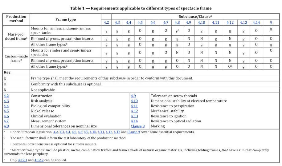
The requirements applicable to different types of spectacle frames are given in Table 1.
All spectacle frame types covered by this document shall comply with the requirements identified as “general (g)”. Requirements marked “O” are optional, but may be required by legislation in some countries.
In some regions, local legislation requires a spectacle frame model to comply with regulatory requirements throughout the duration of its supply to the market.
When conformity with this document is claimed, the manufacturer or its representative has the responsibility—by any chosen means—to ensure that the compliance of the spectacle frame model continues throughout its duration of supply, and not only at its first launch on the market.
4 Requirements
4.2 Construction
The solutions adopted by the manufacturer for the design and construction of spectacle frames shall conform to safety principles, taking account of the generally acknowledged state of the art.
When tested under the inspection conditions given in 7.2, areas of the spectacle frame that might, during intended use, come into contact with the wearer shall be smooth and without sharp protrusions.
NOTE 1: If a frame incorporates magnets (e.g. for attachment of clip-ons or prescription inserts), the risk management process must ensure that there will not be any interference with other medical devices (e.g. hearing aids), and shall not compromise health (e.g. the possibility of being swallowed). The risk of swallowing magnets by children can be tested, e.g. EN 71-1.
NOTE 2: Legislation in some countries can require that, for example, frames fitted with headbands that help retain the spectacles in the correct position in front of the eyes, the headband shall not be capable of causing a strangulation hazard. See, for example, EN 71-1 and EN 14682.
4.3 Risk Management
Spectacle frames should be designed, manufactured, and packaged so that, when used under normal conditions of use, they shall be safe.
ISO 14971 gives guidance on risk management.
NOTE: In some countries, additional regulations can be relevant, e.g. CPSIA (Consumer Product Safety Improvement Act), or for wearers aged 36 months or less, e.g. Directive 2009/48/EC of the European Parliament and of the Council of 18 June 2009 on the safety of toys.
4.4 Biological Compatibility
When considering the biological properties of frame materials, manufacturers should avoid using substances that are known to be allergenic, carcinogenic, mutagenic, or toxic to reproduction. Attention should be paid to any regulatory limits.
For mixed frames, where more than one material is liable to come into close and prolonged contact with the skin, the manufacturer will have to consider the biological properties of each material.
NOTE 1: In some countries, restrictions on specific materials or their chemical constituents are mandatory, e.g. European REACH, Californian Proposition 65.
NOTE 2: For manufacturer’s convenience, Annex B gives a list of chemicals that could give rise to concern. This list is only an indication, is not comprehensive, is subject to change, and does not give threshold limits. Manufacturers should check their local regulations regularly.
NOTE 3: The following list, which is given for information, provides examples of documents that can be examined when checking the innocuousness of materials:
- Specification of the materials used
- Safety data sheets relating to the materials
- Information relating to the suitability of the materials for use in medical devices or other relevant applications
- Information relating to investigations into the allergenic, carcinogenic, toxicological, or mutagenic properties of the materials, or their toxicity with regard to reproduction
Information relating to ecotoxicological and other environmental investigations on the materials
NOTE 4: Reactions can be generated by excessive pressure (e.g. due to a poor fit on the face), chemical irritation, or allergy. Rare or idiosyncratic reactions can occur to any material and indicate the need for the individual to avoid frames made from that particular material.
NOTE 5: Testing according to ISO 10993 gives useful information on biocompatibility.
4.5 Nickel Release (Optional)
Those parts of metal frames and metal parts of combination frames that come into direct and prolonged contact with the skin of the wearer shall not have a nickel release greater than 0.5 μg/cm²/week (as expressed in the EU's REACH regulation), when tested in accordance with EN 16128.
The parts to be tested are specified in EN 16128 and shall include the following:
The front (rims, bridge, and, if applicable, race bar and any nasal bearing surfaces including metal nose pads), excluding pad arms and lugs
The sides including metal collets, excluding joints and areas intended to be protected by plastic end covers (tips)
Metal decorative trims, if fitted on the inside of plastic sides and plastic end covers
NOTE 1: Annex C provides brief information about European requirements and legislation.
NOTE 2: If only indicative information on the extent of nickel release is required, such information can be obtained by performing one of the tests specified in CEN/TR 12471. See NOTE 2 of Annex C.
4.6 Clinical Evaluation
If a spectacle frame is manufactured using materials (e.g. plastics, alloys, coatings, or pigments) not previously used in spectacle frame manufacture, the clinical evaluation shall be made according to the appropriate International Standard(s), either:
Using the spectacle frame itself, or
Using studies where the identical material is used in other medical devices
4.7 Measurement System
The stated nominal dimensions of the spectacle frame shall be in accordance with the measuring system specified in ISO 8624.
4.8 Dimensional Tolerances on Nominal Size
When measured with a linear measuring device with an uncertainty no greater than ±0.1 mm, the following tolerances shall apply to the marked dimensions of the unglazed spectacle frame using the boxed lens measurement method described in ISO 8624:
a) Horizontal boxed lens size: ±0.5 mm
b) Distance between lenses: ±0.5 mm
c) Overall length of side: ±2.0 mm
To improve the accuracy of measurement of overall length of side, it is recommended that the drop be physically straightened.
Sinuosity in the intended vertical plane, or pronounced curvature in the intended horizontal plane in the part of the side before the ear bend, should be ignored.
The overall length of side should be taken as the length of the straight line between the axis of the joint (hinge) or dowel screw’s axis and the end of the side. See ISO 8624:2020, Figure 2, for an illustration of overall length of side.
Gentle bowing of the side to go around the width of the head should be straightened.
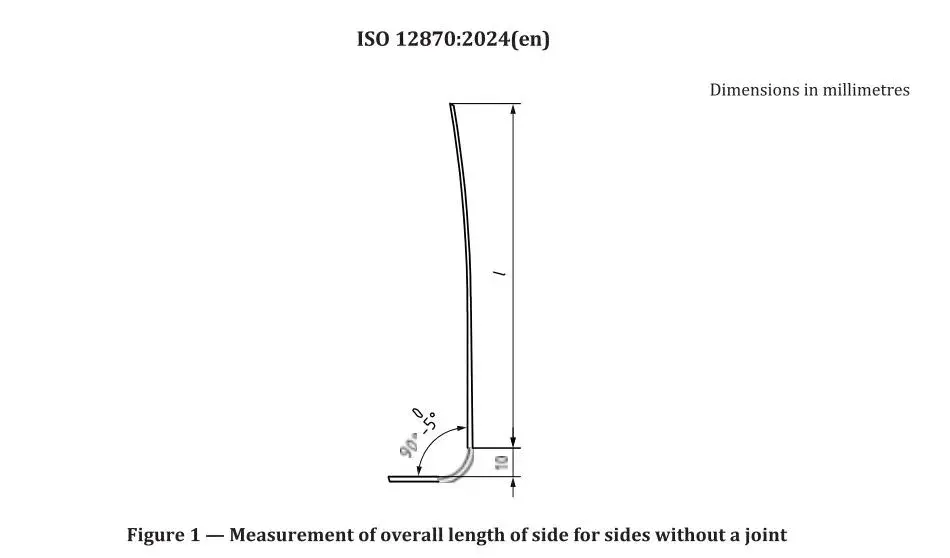
For sides without a hinged joint, the side should be held open at 90° to the front or to that part of the side that is attached to the front, and the length measurement is from the end of the side to the back surface of the lug, less 10 mm. See Figure 1 for an illustration of overall length of side.
4.9 Tolerance on Screw Threads (Optional)
To simplify the edging of lenses for any single frame model, tighter tolerances in the lens aperture size from one frame to another of the same nominal size may be a matter of agreement between supplier and purchaser.
It is recommended that the screw threads used in spectacle frame manufacture are chosen from those in ISO 11381, but this should not restrict future frame development.
The tolerances on the screw threads used in the spectacle frame should conform to ISO 11381.
4.10 Dimensional Stability at Elevated Temperature
When the spectacle frame with test lenses fitted is tested in accordance with 8.2, the distance between the tips of the sides shall not alter by more than:
+6 mm or –12 mm
For small spectacle frames, where the tip of the side is less than 100 mm from the back plane of the front, these tolerances are reduced to:
+5 mm or –10 mm
4.11 Resistance to Perspiration
When the spectacle frame is tested in accordance with 8.3, there shall be:
a) No spotting or obvious alteration in colour (except for loss of gloss to the surface) anywhere on the frame
b) No corrosion, surface degradation (e.g. roughness, orange peel appearance), or separation of any coating layer on the parts liable to come into prolonged contact with the skin during wear, i.e.:
The insides of the sides
Bottom and lower parts of the rim
Inside of the bridge
These conditions apply after testing for a total of 24 hours.
The labelling of manufacturer/brand, model, and size should still be legible after testing for 8 hours.
Such defects shall be visible to a trained observer under the inspection conditions described in 7.2.
If the spectacle frame is made from natural organic materials, and the manufacturer recommends use of a product such as a cream or wax for its maintenance, then before testing, the frame(s) shall be prepared with this product in accordance with the manufacturer’s instructions.
At the end of the test, if the frame fails to meet this requirement when checked for colour change or surface degradation, the use of the product and its effect shall be taken into account.
Wait for one day before checking again for colour change or surface degradation. If the frame has recovered its original colour and surface finish, the spectacle frame is considered to have passed the test. If the frame remains discoloured, the frame is considered to have failed the test.
If the spectacle frame is fitted with readily interchangeable soft nose pads or end covers (side tips), and at the end of the 24-hour test the frame would have passed the test but these components have changed appearance without surface degradation, then the spectacle frame is considered to have passed the test.
4.12 Mechanical Stability
4.12.1 Bridge Deformation
When tested in accordance with 8.4, the spectacle frame with the test lenses fitted shall not:
a) Fracture or crack at any point
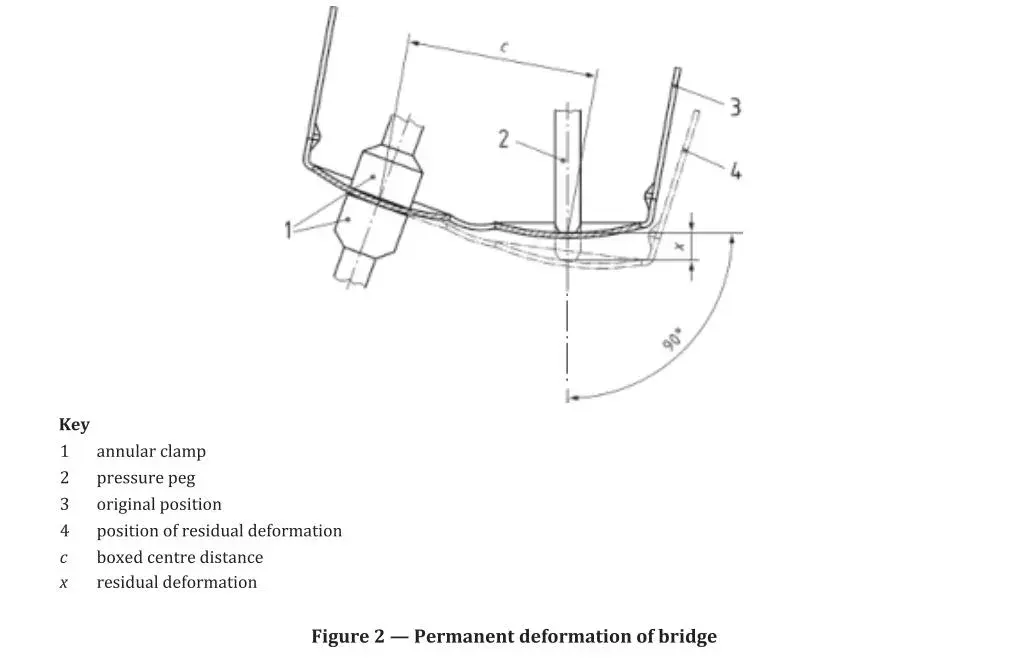
b) Be permanently deformed from its original configuration by more than 2% of the distance c between the boxed centres (see ISO 8624) of the spectacle frame, i.e. the residual deformation x shall not exceed 0.02c (see Figure 2)
4.12.2 Lens Retention Characteristics
The spectacle frame shall be considered to demonstrate acceptable lens retention characteristics if, when tested in accordance with 8.4, neither test lens is dislodged wholly or partially from its original location in the groove or mount.
4.12.3 Endurance
This test aims to simulate the strains on the frame, particularly the joints, when putting the spectacles on or off.
The end of one side is rotated through a circle of diameter 60 mm
The end of the other side is clamped to a universal joint, the other end of which is fixed, allowing vertical and horizontal angular but not twisting rotational movements
The bridge is supported, but not clamped, by an artificial nose to restrict movement of the frame
When tested in accordance with 8.5, the spectacle frame with the test lenses fitted shall not:
a) Fracture at any point
b) Be permanently deformed from its original position by more than 5 mm after 500 cycles
c) Require more than light finger pressure to open and close the sides (except for frames fitted with sprung joints)
d) Have a side that closes under its own weight at any point in the opening/closing cycle (for frames not in the open position, i.e. opened to the fullest natural extent without activating the spring mechanism)
4.13 Resistance to Ignition
When the spectacle frame is tested in accordance with 8.6, there shall be no continued combustion after withdrawal of the test rod.
4.14 Resistance to Optical Radiation (Optional)
When tested in accordance with 8.7, there shall be no:
a) Colour change greater than grade 3 on the grey scale in ISO 105-A02
b) Loss of lustre on bright surfaces
When compared with an untested sample under the inspection conditions described in 7.2.
5 Selection of Test Samples
5.1 General
The minimum level of conformity testing requires that two test specimens of each spectacle frame model shall be selected at random. These specimens shall be selected by the manufacturer or its representative and shall be identified as test sample 1 and test sample 2. They shall be conditioned as described in Clause 6 before testing as described in Clauses 7 and 8.
5.2 Testing for Nickel Release
For metal, combination, and mixed frames that are subject to Clause 4.5, two additional test samples shall be selected at random and shall be conditioned and tested as specified in EN 16128.
5.3 Change in Spectacle Frame Model
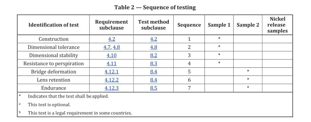
If a range of spectacle frame models is made from the same material(s), following the same manufacturing procedures including surface treatments, it is acceptable to perform, from Table 2, test sequences:
- 4 (see 8.3)
- 8 (see 8.6)
- and, if required, 9 (see 8.7)
on only one of the frame models.
6 Preparation and Conditioning of Test Samples
6.1 Test Lenses
Prior to testing for the requirements described in Clauses 4.10 to 4.14, test samples 1 and 2 shall be fitted with a pair of suitable test lenses.
The test lenses should be supplied or specified by the manufacturer, importer, or authorized representative.
If test lenses are not supplied or specified, then the testing laboratory shall contact the frame manufacturer to obtain the edge profile.
In the absence of supply or specifications from the manufacturer, or an inability to contact the manufacturer, test lenses are recommended to be:
Of suitable material for the type of frame
Have a vertex power of (0.00 ± 0.25) D
Have a centre thickness of (2.00 ± 0.2) mm
Have a curvature appropriate for the frame
For all test samples, these test lenses shall be edged either:
In accordance with the manufacturer’s electronic instructions, or
With a digitally controlled edging machine that uses the tracing made of the individual test sample, or
Where appropriate, using a mechanical former in accordance with ISO 11380
NOTE: These test lenses can also be used for any test samples required for nickel release testing.
6.2 Sample Conditioning and Test Conditions
Immediately before starting the series of tests, the test samples shall be conditioned for at least 4 hours at an ambient temperature of (23 ± 5) °C, in the condition as received from the manufacturer or supplier, without prior realignment, adjustment, or lubrication.
Testing shall be carried out in an atmosphere maintained within the same temperature range.
7 Testing, Inspection and Conformity
7.1 Testing
The testing shall be carried out with the conditioned test samples (see 6.2) in the sequence specified in Table 2, at an ambient temperature of (23 ± 5) °C.

7.2 Inspection and Examination
Where visual inspection is required, the inspection and examination of test samples shall be carried out without magnification, by a trained observer.
During the examination:
Expose the test specimen (and, if specified, the reference specimen) to an illuminance of 1000 lx to 2000 lx
Carry out the inspection against a matt black background
7.3 Conformity
If all test samples of the spectacle frame model pass the tests specified in Table 1 and in the sequence listed in Table 2, the product shall be deemed to comply with this document (see Figure 3).
If either sample 1 or sample 2 fails any one of the tests in the complete test sequence:
An additional sample shall be used to repeat the test that was failed
If this additional sample passes the previously failed test and subsequent tests specified in Table 1 and listed in Table 2, the product shall be deemed to comply with this document
If one or more tests in the sequence result in failure, the product shall be deemed not to comply
If two or more of the tests carried out on the first set of test samples result in failure:
No additional samples shall be tested
The product shall be deemed not to comply with this document
In the case of non-conformity, this clause does not preclude resubmitting the frame for testing after improvements have been made to its design or manufacture.
8 Test Methods
8.1 General
The test methods described are reference test methods. Variations or alternatives may be used, provided their results can be shown to be equivalent to those of the relevant reference method.
In case of dispute, the result obtained with the reference method shall have precedence.
8.2 Test for Dimensional Stability
8.2.1 Apparatus
8.2.1.1 Oven capable of producing the test temperature of (55 ± 5) °C
8.2.1.2 Flat plate of glass or metal, mounted in the oven either on or parallel to the base of the chamber
8.2.1.3 Linear measuring device with uncertainty no greater than ±0.5 mm
8.2.2 Procedure
8.2.2.1 At ambient temperature (23 ± 5) °C, take test sample 1 (with test lenses fitted and sides opened to the fullest extent).
For frames with sprung joints, open to the fullest natural extent without activating the spring mechanism
Measure the distance between the side tips using the measuring device (8.2.1.3)
Record this measurement as the pre-heating value, l
8.2.2.2 Stabilize the oven at the test temperature of (55 ± 5) °C
Place the test sample on the plate (8.2.1.2), with the sides still open and the top edge of the front and sides resting on the plate surface
Ensure the sample does not touch other samples or the oven wall
8.2.2.3 After approximately 15 minutes at test temperature:
Remove the test sample (still on the plate) from the oven
Allow to cool for at least 2 hours at (23 ± 5) °C
Repeat the measurement of the distance between the side tips as described in 8.2.2.1
Record this as the post-heating value and calculate the difference
Compare the result against the requirement in Clause 4.10
8.3 Test for Resistance to
8.3.1 Apparatus and Reagents
8.3.1.1 Oven capable of producing the test temperature of (55 ± 5) °C
8.3.1.2 Container of glass or inert plastic, measuring at least 200 mm across and 90 mm high, capable of being closed
8.3.1.3 Volumetric flask, 1 L, gauged to Class A of ISO 1042
8.3.1.4 Water conforming to Grade 3 of ISO 3696
8.3.1.5 Artificial sweat solution, comprised of:
a) Lactic acid, >85% mass fraction purity
b) Sodium chloride of recognized pro analysis (PA) grade or better
c) Water conforming to Grade 3 of ISO 3696
Preparation of solution: Using suitable containers, weigh (50 ± 0.1) g of lactic acid and (100 ± 0.1) g of sodium chloride. Dissolve in 900 ml of water. Using the flask (8.3.1.3), make up to 1 L with water.
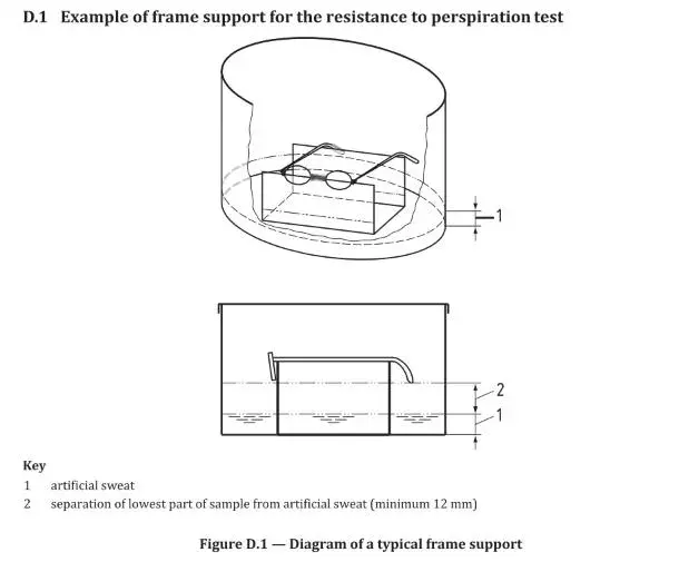
8.3.1.6 Frame supports of glass or inert plastic, fitted in the container so that the sample(s) are held at no less than the specified distance above the artificial sweat solution (see 8.3.2.1 and Figure D.1).
Supports can be designed to hold several samples stacked one above another, side by side, or both
Samples must not be in contact with each other
8.3.2 Procedure — Resistance to Perspiration
- Cover the base of the container with the artificial sweat solution to a minimum depth of 10 mm, ensuring the lowest part of the frame is not less than 12 mm above the solution.
- Place test sample 1 on the supports with sides fully opened. Ensure it does not touch other samples or container walls. Close the container, place it in the oven, and maintain at (55 ± 5) °C.
- After (8 ± 0.5) hours, remove and rinse each sample with water. Dry gently with a soft cloth.
- Within 30 minutes, inspect each sample under specified conditions and compare with an untested frame.
- Replace the sample, close the container, and continue heating for (16 ± 0.5) hours. Then remove, clean, and dry as before.
- Within 30 minutes, inspect areas in contact with skin for corrosion, degradation, or coating separation.
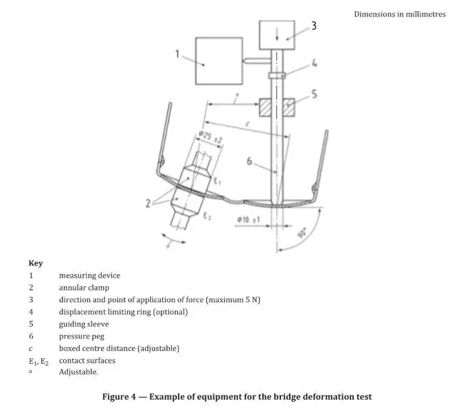
8.4 Bridge Deformation and Lens Retention
8.4.1 Apparatus
- Annular Clamp: Holds the frame without twist/slip; diameter 252 mm; rotatable for face form angle.
- Pressure Peg: Vertical movement; diameter (10 ± 1) mm; hemispherical tip.
- Measuring Device: Accuracy ±0.1 mm for displacement measurement.
8.4.2 Procedure
- Mount test sample 2 with front facing down. Clamp near boxed centre.
- Lower pressure peg to rest on lens. Record starting position.
- Apply force until:
- Maximum 5 N, or
- Displacement = (10 ± 1)% of boxed centre distance (c)
- Maintain force/displacement for 5 seconds, then release. After 20 seconds, re-measure final position.
- Calculate deformation:
f = (x × 100) / c - Inspect for lens dislodgement under standard conditions.
8.5 Endurance Test
8.5.1 Apparatus
- Two clamping devices on universal joints
- Bridge support and revolution counter
Motion cycle:
- Down: (30 ± 0.5) mm
- Out: (60 ± 1.0) mm
- Up: (30 ± 0.5) mm
at 40 cycles/min
Manufacturers may modify the setup to test either side independently.
8.5.1.2 Clamping Devices
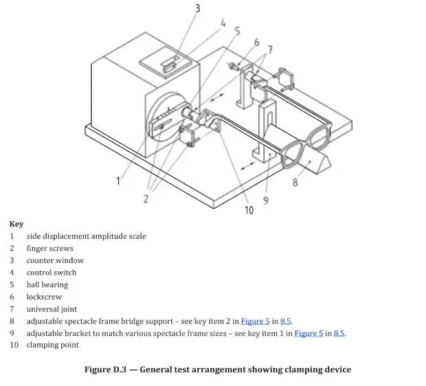
Clamping devices, mounted on universal joints, are used to restrain the sides (see Figures D.2 and D.3). The universal joints shall not restrict the angular movement of the sides. The clamping point, specified as the edge of the clamp nearest the axis of the joint (hinge) or dowel screw's axis, shall be (55 ± 1) mm from the centre of the pivot of the universal joint.
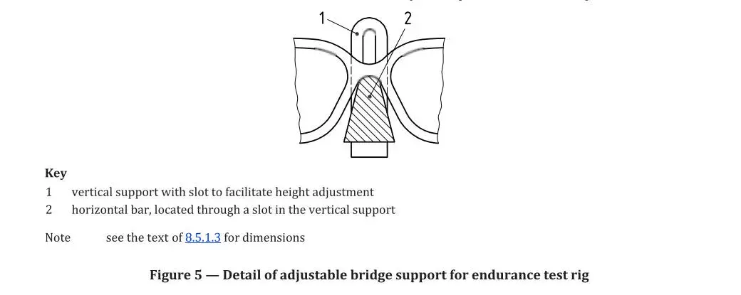
8.5.1.3 Bridge Support
Formed from a horizontal bar of triangular cross-section, enclosing an angle of (30 ± 2) and having a thickness at the top of (12 ± 1) mm with the upper edge approximately radiused (see Figure 5, key item 2).
8.5.1.4 Revolution Counter
Used to count the number of cycles imparted to one of the spectacle sides.
8.5.2 Procedure
8.5.2.1 Clamping and Measuring Points
Before mounting test sample 2 on the test apparatus, establish the clamping and measuring points:
- For standard sides: clamp at (70% ± 1 mm) of overall side length from the joint axis; measuring point is (15 ± 1) mm nearer to the joint axis than the clamping point.
- For curl sides: clamp point is 31 mm nearer to the joint axis than the curl junction; measuring point is (10 ± 1) mm nearer than the clamp point.
- For sides without a joint: reference point is (10 ± 1) mm from the back surface of the lug (see Figure 1).
8.5.2.2 Mounting and Setup
Open the sides fully without tension and measure the distance d between the sides at the measuring points. Mount the frame and ensure:
- a) Rotating clamp is aligned with the fixed clamp and at its nearest rotation point.
- b) Bridge is freely supported on the bridge support.
- c) Horizontal alignment places the bridge support midway between clamps.
- d) Bridge support height ensures side alignment with clamp axis and base.
- e) Sides are clamped within 1 mm of calculated clamping point.
- f) Lock screw is loosened and re-tightened to allow proper side angle alignment.
- g) Revolution counter is set to zero.
8.5.2.3 Execution
With test lenses fitted, run the apparatus for up to 5 cycles. If the bridge lifts off the support, add an elastic retaining band. Continue to a total of (500 ± 1) cycles. After completion:
- Stop motion and remove sample.
- Check that the difference between initial and final d does not exceed 5 mm.
- Inspect for fractures, cracks, or changes in side movement (see 4.12.3).
8.6 Test for Resistance to Ignition
8.6.1 Apparatus
- 8.6.1.1 Steel rod: (300 ± 3) mm long, (6.0 ± 0.5) mm diameter, flat end faces.
- 8.6.1.2 Heat source.
- 8.6.1.3 Thermocouple and temperature-indicating devices.
- 8.6.1.4 Timer: measures up to 10.0 s with ±0.1 s resolution.
8.6.2 Procedure
- Do not test batteries or electronic parts likely to explode.
- Heat one end of the steel rod to (650 ± 20) °C over at least 50 mm length.
- For routine testing, preheat to ~900 °C, then allow cooling to target temperature.
- Use thermocouple at (20 ± 1) mm from heated end to monitor cooling.
- Record time taken for rod to cool to test temperature.
- Use known heating/cooling curves to avoid repeated temperature measurements during contact.
8.6.2.1 Procedure
Press the heated face of the steel rod (long axis vertical, heated end downwards) against the surface of test sample 1. The contact force should equal the weight of the steel rod. Maintain contact for (50 ± 0.5) seconds, then remove the rod. Carry out the test on all externally exposed materials of the frame.
8.6.2.2 Visual Inspection
Carry out a visual inspection during the test to determine whether the test sample ignites or continues to glow after removal of the rod (see 4.13).
8.7 Test for Resistance to Optical Radiation
8.7.1 Apparatus
- 8.7.1.1 Fused-silica envelope, ozone-free, high-pressure xenon lamp:
- a) Reference method: 450 ± 50 W lamp, ≥30% transmittance at 200 nm, burned in ≥150 h, max 2000 h use
- b) Alternative method: other power xenon lamps, same burn-in and max usage limits
- 8.7.1.2 Long wavelength pass (cut-on) filter: cut-on wavelength = 320 nm at 46% transmittance, ±5 nm shift allowed
- 8.7.1.3 Standard blue-scale radiation exposure medium (optional), conforming to ISO 105-B02
8.7.2 Procedure
8.7.2.1 Reference Procedure
- Cut test sample 2 at bridge midpoint; retain one part as control
- Separate side from front on test part
- Stabilize lamp current at (25.0 ± 0.2) A
- Maintain air temperature at (28 ± 5) °C with forced ventilation
- Expose front and side surfaces to radiation from lamp (8.7.1.1a) filtered by filter (8.7.1.2)
- Angle of incidence: perpendicular; distance from lamp axis: (300 ± 10) mm
- Exposure time: (25.0 ± 0.2) hours at 450 ± 50 W
8.7.2.2 Alternative Procedure
- Same sample preparation as reference method
- Expose surfaces and blue-scale medium to lamp (8.7.1.1b) filtered by filter (8.7.1.2)
- Continue until blue-scale medium reaches stage 4.5 on grey scale (see ISO 105-B02)
- Maintain air temperature at (28 ± 5) °C with forced ventilation
- Radiation time: between 10 h and 50 h
8.7.2.3 Post-Test Inspection
Switch off radiation, remove samples, and inspect under conditions in 7.2. Ignore changes near the cut surface. Compare exposed sample to control. Record as failure if any changes specified in 4.14 are observed.
9 Marking
Spectacle frames shall be marked, usually on the sides, with the following minimum information:
- a) Manufacturer or agent/supplier identification
- b) Model identification
- c) Colour identification
- d) Horizontal boxed lens size with box symbol
- e) Distance between lenses
- f) Overall length of side
NOTE 1: All dimensions are defined in ISO 8624.
NOTE 2: Marking of horizontal boxed lens size is optional for rimless mounts.
NOTE 3: National legislation may require additional markings such as country of origin or regulatory conformity. Frames may also need to be labelled as medical devices, either on the frame or packaging.
The specified order of marking dimensions is shown in Figure 6.
10 Additional Information to Be Supplied by the Manufacturer or Other Person Placing the Product on the Market
Information should include any special processing conditions required for lens fitting or frame adjustment.
NOTE: Labelling symbols, lot numbers, etc., are covered in ISO 15223-1 and ISO 20417. Annex E (optional) allows manufacturers to provide details such as adjustment temperatures, chemicals to avoid, and cleaning instructions.
10.2 Catalogue Information
Available range (sizes and colours), including other side lengths.
10.3 Information Available Upon Request
- a) Vertical boxed lens size (ISO 8624)
- b) Bridge width (ISO 8624)
- c) Bridge height (ISO 8624)
- d) Frame effective diameter (ISO 8624)
- e) Apex angle for groove if bevel angle ≠ 120°
- f) List of separately available components
10.4 Legal Requirements
Some countries require the frame or packaging to state the name and address of the manufacturer or authorized representative.
11 Reference to This Document
If the manufacturer or supplier claims conformity with this document, reference shall be made either on the packaging or in available literature. Marking "ISO 12870" on the frame is optional.
Any claim for conformity with optional subclauses (e.g. 4.14) shall be accompanied by a reference to this document, i.e. ISO 12870:2024. If clause 4.5 (nickel release) applies, reference to EN 16128 shall also be included.
Annex A (Informative)
Recommendations for the Design of Spectacle Frames
A.1 Design
The spectacle frame should securely hold lenses in the prescribed position relative to the eyes and be comfortable for prolonged wear. In addition to meeting the requirements of this document, the frame should have the following capabilities.
A.2 Materials
Materials should be stable (see Clause 4), allow professional adjustment, retain shape and position when worn, and resist degradation over time.
Information that can be provided includes:
- Type of plastic and whether it has a coating
- For metal frames:
- a) Rolled-gold covering (see 3.3.2) or titanium material (see 3.3.4)
- b) Type of base material, plating, and protective/decorative coating
A.3 Assembly
Assembly should prevent unintentional separation of components during fitting or normal wear.
A.4 Range of Sizes and Adjustment
A.4.1 Fronts
Frames should be available in at least two lens sizes, each with two bridge widths.
A.4.2 Sides
Side length should be adjustable. Manufacturers should offer at least three side lengths with 5 mm differences, or design metal sides to be easily shortened under end covers.
A.5 Mass
Recommended maximum mass of unglazed frame: 32 g.
A.6 Contact Areas
Bearing surfaces should be as large as reasonably possible. Suggested pad/nasal area:
- a) ≥175 mm² for frames ≤25 g
- b) ≥250 mm² for frames >25 g
A.7 Sprung Joints
Spring tension should be symmetrical and activate immediately at the side tip when deflected.
A.8 Symmetry
In mirror-symmetric designs, let-back, angle, and side length should be equal.
A.9 Claims for Material Composition
A.9.1 General
Frames claimed to be made from rolled-gold or titanium must comply with Clause 3 definitions.
A.9.2 Use of Titanium in Frames
Titanium components should be marked (e.g., “F-Ti”, “S-Ti”) and have non-nickel coatings. They must comply with definitions for:
- Titanium frame
- Pure titanium frame
- Memory-metal frame
- Titanium niobium frame (Ti-Nb frame)
Annex B (Informative)
Chemicals That Can Be Harmful to Health
This list is indicative, not comprehensive, and does not specify thresholds. Manufacturers should check local regulations regularly.
- Heavy metals
- Alkyl-Phenols & Alkyl-Phenols Ethoxylates (APs & APEOs)
- Azo Dyes
- Allergenic & Carcinogenic dyes
- Bisphenols
- Chlorinated Paraffins
- Chlorinated Phenols and Ortho-Phenylphenols
- Chlorinated Carriers (Chlorobenzenes and Chlorotoluenes)
- Biocides & Preserving Agents
- Formaldehyde
- Nitrosamines
- Organotin Compounds
- Perfluorinated & Polyfluorinated Chemicals (PFCs)
- Phthalates
- Polycyclic Aromatic Hydrocarbons
- Quinoline
- Solvent Residuals
- UV Stabilizers
- Volatile Organic Compounds (VOCs) & Chlorinated Solvents (CVOCs)
- Monomers
Annex C (Informative)
European Requirements and Legislation on Nickel Release
European legislation refers to the following standards:
- EN 1811 — Reference test method for nickel release from items inserted into pierced body parts or in prolonged skin contact
- EN 12472 — Simulation of wear and corrosion for detecting nickel release from coated items
- EN 16128 — Reference method for testing spectacle frames and sunglasses for nickel release
Of these, EN 12472 and EN 16128 apply to spectacle frames.
NOTE 1: EN 16128 uses the wear simulation test from EN 12472, which is why EN 12472 is not directly referenced in the main document.
NOTE 2: For a simple indication of nickel release compliance, the DMG test in CEN/TR 12471 may be used. This test forms a colored complex when nickel ions contact a mixture of ammonia and dimethylglyoxime. If the cotton bud turns pink, there is a significant probability of compliance with Clause 4.5.
Annex D (Informative)
Examples of layout of test equipment
D.2 Examples of the equipment layout for the endurance test
NOTE: for testing in frame development, manufacturers might wish to modify the test equipment so that either the right or the left side can be subject to the cyclical motion, the other remaining fixed.