BS EN ISO 8624 - Spectacle Frames Measuring System and Terminology
Ophthalmic optics - Spectacle Frames - Measuring system and terminology (ISO 8624:2011)
National foreword
This British Standard is the UK implementation of EN SIO 8624:2011+A1:2015. It supersedes BS EN ISO 8624:2011 which is withdrawn.
The start and finish of text introduced or altered by amendment is indicated in the text by tags. Tags indicating changes to ISO text carry the number of ISO amendment. For example, text altered by ISO amendment 1 is indicated by A1.
The UK participation in its preparation was entrusted by Technicail Committee CH/172, Ophthalmic Optics, to Subcommittee CH/172/3, Spectacles.
A list of organizations represented on this subcommittee can be obtained on request to its secretary.
This publication does not purport to include all the necessary provisions of a contract. Users are responsible for its correct application.
© The British Standards Institution 2015.
Published by BSI Standards Limited 2015
ISBN 978 0 580 82849 0
ICS 11.040.70
Compliance with a British Standard cannot confer immunity from legal obligations.
This British Standard was published under the authority of the Standards Policy and Strategy Committee on 28 February 2011.
Amenments/corrigenda issued since publication
| Date | Text affected | |
|---|---|---|
| 30 September 2015 | Implementation of ISO amendment 1:2015 with CEN endorsement A1:2015 |
Ophthalmic optics - Spectacle frames - Measuring system and terminology (ISO 8624:2011)
This European Standard was approved by CEN ON 5 February 2011.
CEN members are bound to comply with the CEN/CENELEC Internal Regulations which stipulate the conditions for giving this European Standard the status of a national standard without any alteration. Up-to-date lists and bibliographical references concerning such national standards may be obtained on application to the CEN-CENELEC Management Centre or to any CEN member.
This European Standard exists in three official versions (English, French, German). A version in any other language made by translation under the responsibility of a CEN member into its own language and notified to the CEN-CENELEC Management Centre has the same status as the official versions.
CEN members are the national stantards bodies of Austria, Belgium, Bulgaria, Croatia, Cyprus, Czech Republic, Denmark, Estonia, Finland, France, Germany Greece, Hungary, Iceland, Ireland, Italy, Latvia, Lithuania, Luxembourg, Malta, Netherlands, Norway, Poland, Portugal, Romania, Slovakia, Slovenia, Spain, Sweden, Switzerland and United Kingdom.
Foreword
This document (EN ISO 8624:2011) has been prepared by Technical Committee ISO/TC 172 “Optics and photonics” in collaboration with Technical Committee CEN/TC 170 “Ophthalmic optics,” the secretariat of which is held by DIN.
This European Standard shall be given the status of a national standard, either by publication of an identical text or by endorsement, at the latest by August 2011, and conflicting national standards shall be withdrawn at the latest by August 2011.
Attention is drawn to the possibility that some of the elements of this document may be the subject of patent rights. CEN [and/or CENELEC] shall not be held responsible for identifying any or all such patent rights.
This document supersedes EN ISO 8624:2002.
According to the CEN/CENELEC Internal Regulations, the national standards organizations of the following countries are bound to implement this European Standard: Austria, Belgium, Bulgaria, Croatia, Cyprus, Czech Republic, Denmark, Estonia, Finland, France, Germany, Greece, Hungary, Iceland, Ireland, Italy, Latvia, Lithuania, Luxembourg, Malta, Netherlands, Norway, Poland, Portugal, Romania, Slovakia, Slovenia, Spain, Sweden, Switzerland, and the United Kingdom.
Endorsement Notice
The text of ISO 8624:2011 has been approved by CEN as EN ISO 8624:2011 without any modification.
Foreword to Amendment A1
This document (EN ISO 8624:2011/A1:2015) has been prepared by Technical Committee ISO/TC 172 “Optics and photonics” in collaboration with Technical Committee CEN/TC 170 “Ophthalmic optics,” the secretariat of which is held by DIN.
This Amendment to the European Standard EN ISO 8624:2011 shall be given the status of a national standard, either by publication of an identical text or by endorsement, at the latest by February 2016, and conflicting national standards shall be withdrawn at the latest by February 2016.
Attention is drawn to the possibility that some of the elements of this document may be the subject of patent rights. CEN [and/or CENELEC] shall not be held responsible for identifying any or all such patent rights.
According to the CEN-CENELEC Internal Regulations, the national standards organizations of the following countries are bound to implement this European Standard: Austria, Belgium, Bulgaria, Croatia, Cyprus, Czech Republic, Denmark, Estonia, Finland, Former Yugoslav Republic of Macedonia, France, Germany, Greece, Romania, Slovakia, Slovenia, Spain, Sweden, Switzerland, Turkey, and the United Kingdom.
Endorsement Notice
The text of ISO 8624:2011/Amd1:2015 has been approved by CEN as EN ISO 8624:2011/A1:2015 without any modification.
Ophthalmic Optics — Spectacle Frames — Measuring System and Terminology
1 Scope
This International Standard specifies a measuring system for spectacle frames and related terminology. It is applicable to fronts which are intended to be symmetrical.
2 Terms, Definitions and Symbols
For the purposes of this document, the following terms, definitions and symbols apply. For complementary terms and definitions, see Annex A.
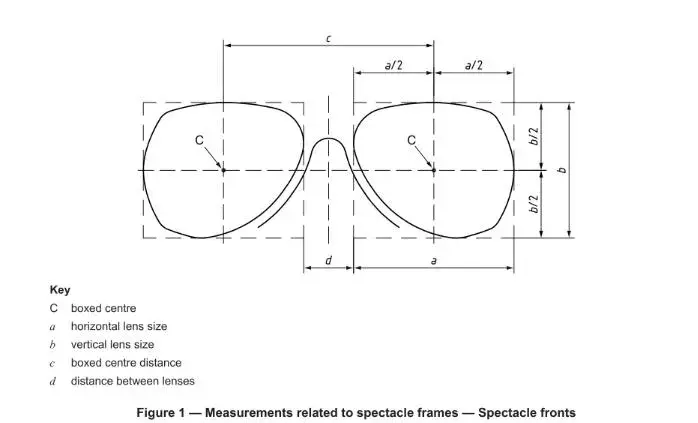
2.1 Boxed Centre (C)
The intersection of the horizontal centreline (A.1) and vertical centreline (A.2) of the rectangular box which circumscribes the lens shape (A.10). See Figure 1.
2.2 Horizontal Boxed Lens Size (Horizontal Lens Size)
The distance between the vertical sides of the rectangular box which circumscribes the lens shape (A.10). See Figure 1.
Note: For spectacle frames having a significant face form angle (A.13), the horizontal boxed lens size shall be measured in the “plane” of the individual lens shape.
2.3 Vertical Boxed Lens Size (Vertical Lens Size, b)
The distance between the horizontal sides of the rectangular box which circumscribes the lens shape (A.10). See Figure 1.
2.4 Boxed Centre Distance (Distance Between Centres)
The distance between the boxed centres (2.1). See Figure 1.
2.5 Distance Between Boxed Centres (Boxed Centre Distance)
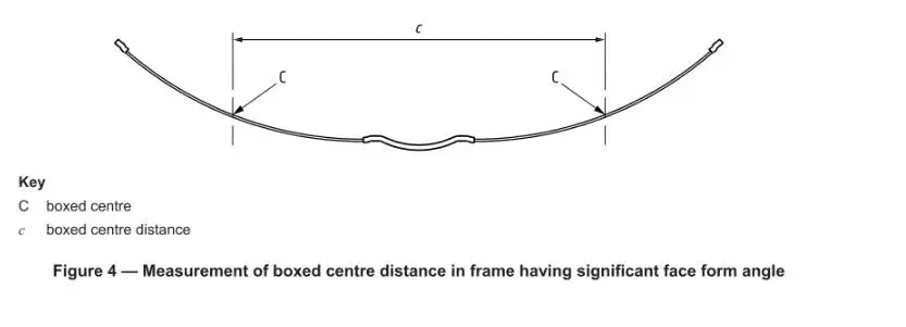
Note: For spectacle frames having a significant face form angle (A.13), the boxed centre distance shall be measured between the boxed centres (2.1) marked on the back surfaces of lenses of appropriate base curve fitted to the frame. See Figure 4.
2.6 Distance Between Lenses (d)
The horizontal distance between the nasal vertical sides of the rectangular boxes which circumscribe the right and left lens shapes (A.10). See Figure 1.
Note: Former users of the obsolete datum system should note that this is the datum measurement “minimum between lenses.”
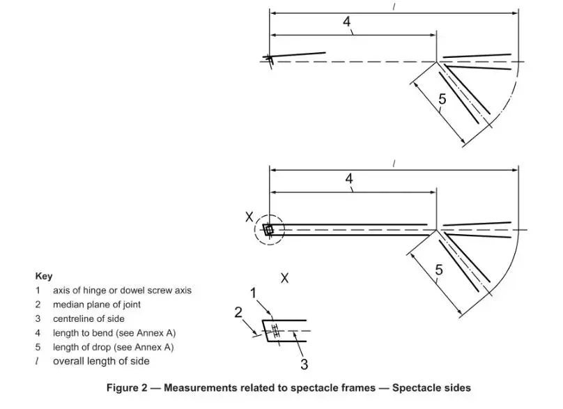
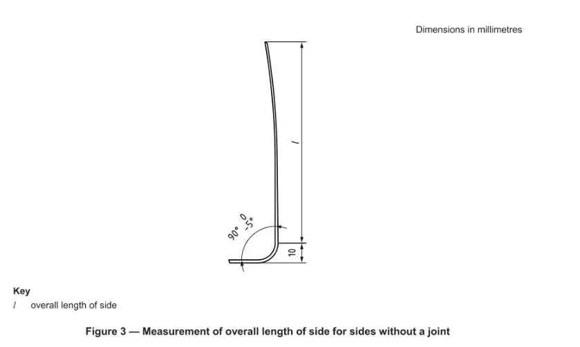
2.7 Overall Length of Side
The length from the intersection of the dowel screw’s axis with the median plane of the joint to the end of the side, measured parallel to the centreline of the side, with the drop having been straightened. See Figure 2.
Note: For sides without a joint, the side should be held open at 90° to the front or to that part of the side that is intended to be attached to the front. The length measurement is from the end of the side to the front, less 10 mm. See Figure 3.
3 Measuring System
The measuring system for spectacle frames shall be in accordance with Figures 1 to 4, as defined in Clause 2.
If codes are used in spectacle frame documentation, the symbols given for the terms defined in Clause 2 shall be employed.
The measuring system comprises several horizontal and vertical dimensions and reference points. Knowledge of these is necessary for the manufacturing, ordering, and adjustment of spectacle frames, as well as for the exact mounting of spectacle lenses into spectacle frames.
The measuring system is based on the boxed lens (boxing) system, which uses a rectangle tangential to the lens shape as the basis for the determination of the dimensions of the spectacle front.
The upper tangent is common to both lens shapes and shall be regarded as horizontal, except in the case of spectacle frames having a significant face form angle. For such frames, the line touching the uppermost edges of the right and left lens shapes shall be regarded as horizontal.
Annex A
(informative)
Complementary Terms and Definitions
Although the terms defined in this annex are not an integral part of the boxed lens system, they are frequently used in relation to lens shape or spectacle frames.
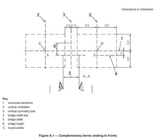
A.1 Horizontal Centreline
Line located at an equal distance from the two horizontal tangents of the boxed lens (boxing) system. See Figures A.1 and A.2.
A.2 Vertical Centreline
Line located at an equal distance from the vertical sides of the rectangular box which circumscribes the lens shape (A.10). See Figure A.1.
A.3 Vertical Symmetry Axis
Line located at equal distance from the nasal vertical sides of the rectangular boxes which circumscribe the right and left spectacle lens shapes (A.10). See Figure A.1.
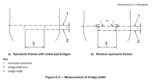
A.4 Bridge Width Line
Reference line for bridge measurements positioned 5 mm below the horizontal centreline (A.1). See Figures A.1 and A.2.
A.5 Bridge Width
Minimum distance between the rims measured along the bridge width line (A.4). See Figures A.1 and A.2.
NOTE: For spectacle frames with adjustable pads, bridge width applies to the rims, not the pads. For rimless spectacles, it applies to the minimum distance between the nasal edges of the spectacle lenses measured along the bridge width line.
A.6 Bridge Height
Distance from the bridge width line (A.4) to the lower edge of the bridge, measured along the vertical symmetry axis (A.3). See Figure A.1.
A.7 Length to Bend
Length from the intersection of the dowel axis with the median plane of the joint to the intersection point of the axis of the tip and side, measured along the axis of the side.
Annex A
(informative)
Complementary Terms and Definitions (continued)
A.8 Length of Drop
Length from the intersection point of the axes of the side and tip to the end of the side. See Figure 2.
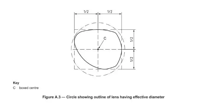
A.9 Effective Diameter
Diameter of the smallest circular uncut lens that can be glazed to the lens shape (A.10), with its geometrical centre positioned at the boxed centre (2.1). See Figure A.3.
NOTE: This includes an allowance for edging.
A.10 Lens Shape
Outline of the lens periphery with the nasal side and the horizontal indicated.
NOTE: “Lens shape” refers to the shape of hypothetical spectacle lenses with:
For a spectacle lens having a bevelled edge: the outermost edge of the spectacle lens, the lens having a bevel which includes a symmetrical angle of 120° and a bevel width greater than the width of the groove in the front.
For a spectacle lens having a flat or grooved edge: the outermost edge of the spectacle lens.
A.11 Plane of the Spectacle Front
Plane containing the vertical centrelines of the right and left boxed lens shapes.
NOTE: This may be an approximation if the two centrelines are not parallel to each other.
A.12 Plane of the Lens Shape
Plane tangential to the front surface of a plano or demonstration (dummy) lens at its boxed centre (2.1), when mounted in the frame.
NOTE: A demonstration lens or dummy lens is the plano lens mounted in the frame by the manufacturer for display purposes.
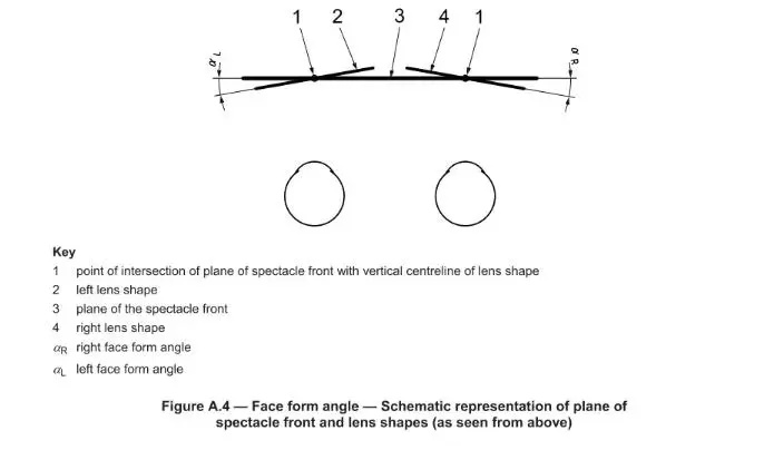
A.13 Face Form Angle
Angle between the plane of the spectacle front and the plane of the right lens shape, or of the left lens shape. See Figure A.4.
NOTE 1: The right or left face form angle is regarded as positive if the temporal side of the right or left lens plane is closer to the head than the plane of the spectacle front (A.11).
NOTE 2: The face form angles are often measured and specified as the average of the right (aR) and left (aL) angles, but the frame may be adjusted for a specific wearer so that they differ, and the angles should then be specified as such.
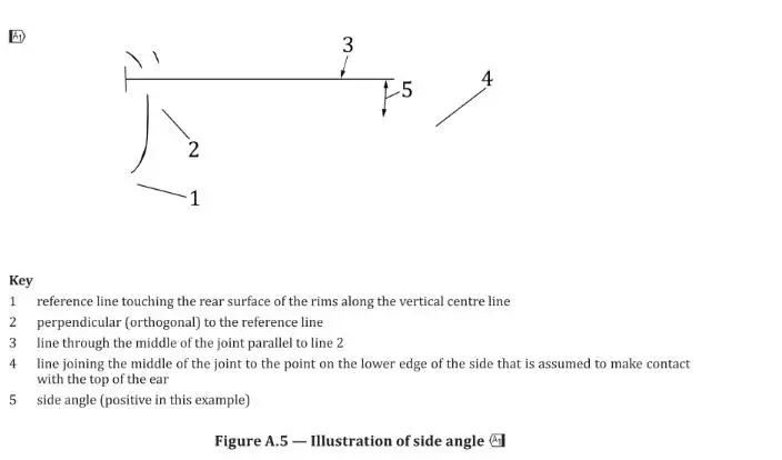
A.14 Angle of Side
(Also referred to as “side angle” in GB and “frame pantoscopic angle” in US)
The angle of side is defined as the angle in the vertical plane, when the side is opened, between:
the perpendicular to a reference line touching the rear surface of the upper and lower rims along their outer edges, and
the line joining the middle of the joint to the point on the lower edge of the side that is assumed to make contact with the top of the ear.
Notes to Entry:
Note 1: See Figure A.5.
Note 2: For spectacle frames of semi-rimless or rimless construction, the reference line should be taken as the line joining the rear surface of the upper and lower edges of a plano, demonstration, or dummy lens along the vertical centreline.
Note 3: Unless otherwise stated, the side angle is regarded as positive if it angles downwards from the perpendicular to the reference line.
Note 4 (from ISO 7998): Equivalent terms in other languages:
French: angle d’inclinaison
German: Inklinationswinkel
Italian: inclinazione
Spanish: inclinación