Non-Prescription Sunglasses & Fashion Eyewear Requirements | ANSI Z80.3 USA Standards Guide
ANSI
Z280.3-2018
Revision of
ANSI Z280.3-2015
American National Standard for Ophthalmics -
Nonprescription Sunglasses and Fashion Eyewear Requirements
Secretariat
The ViSION Council
Approved February 14, 2018
Published March 13, 2018
American National Standards Institute, Inc.
Information from this page is get internet, and use for eyewear professionals for reference only.
Approval of an American National Standard requires review by ANSI that the requirements for due process, consensus, and other criteria for approval have been met by the standards developer.
Consensus is established when, in the judgment of the ANSI Board of Standards Review, substantial agreement has been reached by directly and materially affected interests.Substantial agreement means much more than a simple majority, but not necessarily unanimity.Consensus requires that all views and objections be considered, and that a concerted effort be made towards their resolution.
The use of American National Standards is completely voluntary.Their existence does not in any respect preclude anyone, whether he has approved the standards or not, from manufacturing, marketing, purchasing, or using products, processes, or procedures not conforming to the standards.
The American National Standards Institute (ANSI) does not develop standards and will in no circumstances give an interpretation of any American National Standard. Moreover, no person shall have the right or authority to issue an interpretation of an American National Standard in the name of the American National Standards Institute. Requests for interpretations should be addressed to the secretariat or sponsor whose name appears on the title page of this standard.
CAUTION NOTICE: This American National Standard may be revised or withdrawn at any time.The procedures of the American National Standards Institute require that action be taken periodically to reaffirm, revise, or withdraw this standard. Purchasers of American National Standards may receive current information on all standards by calling or writing the American National Standards Institute.
Developed by:
The Accredited Committee Z80 for Ophthalmic Standards
The Vision Council
225 Reinekers Lane, Suite 700
Alexandria, VA 22314
Published by:
The Vision Council
225 Reinekers Lane, Suite 700
Alexandria, VA 22314
Copyright 2018 by the Vision Council
All rights reserved.
1. What Is ANSI Z80.3 and Why It Matters
1.1 Scope
This standard applies to all nonprescription sunglasses and fashion eyewear, normally used for casual, dress, and recreational purposes, having lenses of substantially plano power.
This standard specifically excludes products covered by:
- ANSI Z87.1 (Occupational safety).
- ANSI Z80.1 (Prescription lenses).
- Those covered within the ASTM F08.57 committee (Specific sports).
Note: Sunglass needs for aphakics (those without a lens in the eye) may not be met by this standard.
1.2 Purpose
The purpose of this standard is to establish standards for:
- Noncorrective (essentially plano power) lenses that are intended for attenuation of light.
- Fashion eyewear.
- The flammability and durability of frames and lenses.
These products are commonly called **sunglasses**.
They are not designed to be:
- Industrial safety eyewear as defined in ANSI Z87.1.
- Provide corrective prescriptions as defined in ANSI Z80.1.
- Provide protection for selected sports as defined within ASTM F08.57 committee standards.
- Provide protection when making direct observation of the sun, such as for viewing a partial or annular solar eclipse.
Low Light Conditions
- Lenses covered by this standard are not intended for use under conditions of reduced illumination.
- However, variable tint lenses that fade to a luminous transmittance greater than 75% are covered.
- Lenses with less than 75% luminous transmittance anywhere on the lenses are not suitable for driving under low light conditions, such as but not limited to twilight or night.
2. US Eyewear Related Standards
The following standards contain provisions that, through reference in this text, constitute provisions of this American National Standard. All standards are subject to revision, and parties to agreements based on this American National Standard are encouraged to apply the most recent editions of the standards indicated below.
| Standard No. | Description | Availability |
|---|---|---|
| ANSI Z80.1 | Ophthalmics - Prescription Ophthalmic Lenses - Recommendations | Available from the American National Standards Institute |
| ANSI Z80.5 | Ophthalmics - Requirements for ophthalmic frames | Available from the American National Standards Institute, 25 West 43rd Street, New York, NY 10036 (Website: webstore.ansi.org). |
| ANSI Z80.17 | Focimeters | Available from the American National Standards Institute |
| ANSI Z87.1 | Occupational and educational eye and face protection devices | Available from the American National Standards Institute |
| ANSI/ASQC Z1.4 | Sampling procedures and tables for inspection by attributes | Available from the American National Standards Institute, 25 West 43rd Street, New York, NY 10036 (Website: webstore.ansi.org). |
| ANSI Z80.3-2018 | (This is the standard identifier itself) | Available from the ASTM International, 100 Barr Harbor Drive, West Conshohocken, PA 19428 (Website: www.astm.org). |
| ASTM D412 | Standard test methods for vulcanized rubber and thermoplastic elastomers - Tension | N/A |
| ASTM D2240 | Standard test method for rubber property - Durometer hardness | Available from the U.S. Government Publishing Office, P.O. Box 979050, St. Louis, MO 63197-9000 (Website: www.gpo.gov) |
| Code of Federal Regulations, Title 21 Part 801.410 | (U.S. Federal Regulation) | N/A |
| ISO 12311 | Personal protective equipment - Test methods for sunglasses and related eyewear | N/A |
| ISO 12312-1 | Eye and face protection - Sunglasses and related eyewear - Part 1: Sunglasses for general use | N/A |
3 Key Definitions in ANSI Z80.3
3.1 Capable of withstanding an impact test
The ability of a lens to withstand impact as determined by 100% testing or by testing of a statistically significant sample (for example, conforming to the requirements of ANSI/ASQC Z1.4) of each production batch, or at the option of the manufacturer, as an integral part of the manufacturing process. Capability of withstanding an impact test is determined by testing at any feasible stage of manufacture, as described in 5.1.1 and 5.1.2.
3.2 Reference point
The point on a lens blank, unmounted lens, or finished lens at which refractive properties, and around which transmittance properties, are specified and measured.
3.2.1 Intended visual axis
When specified, the point on a lens coincident with the wearer’s interpupillary distance or other known or presumed line of sight.
3.2.2 Geometric center
When the intended visual axis is not specified, the geometric center shall be the reference point. The geometric center is the point midway between the two vertical tangents and midway between the two horizontal tangents of the edges of a finished lens. For a one-piece or goggle lens intended to cover both eyes, the vertical midline of the lens may be used to determine the geometric center of the portion of the lens for each eye.
3.3 Lens fracture
A lens is considered to have fractured when it cracks through its entire thickness and across a complete diameter into two or more separate pieces, or when any piece of lens material visible to the naked eye becomes detached from the ocular surface, or if the test ball passes through the lens.
3.4 Lens types
3.4.1 General purpose lens
A lens whose nominal luminous transmittance is at least 8% and that allows the apparent chromaticity of Standard Illuminant D65, when viewed through the lens, to fall within the boundary for daylight (4.10.2.1 part 4, and Figure 1).
3.4.2 Gradient tint lens
A lens whose luminous transmittance varies significantly across the lens.
3.4.3 Photosensitive lens
A lens whose luminous transmittance or color, or both, depends on the recent exposure history of the lens.
3.4.4 Polarizing lens
A lens whose luminous transmittance varies with the amount and orientation of the polarization in the incident light.
3.4.5 Special purpose lens
3.4.5.1 Strongly colored lens
A lens that causes the apparent chromaticity of Standard Illuminant D65, when viewed through the lens, to fall outside of the boundary for daylight (4.10.2.1 part 4, and Figure 1).
3.4.5.2 Very dark lens
A lens whose nominal luminous transmittance is between 3% and 8%.
3.4.6 Uniform tint lens
A lens whose luminous transmittance does not vary significantly over the area of the lens.
3.5 Noncorrective impact-resistant lenses
Glass lenses, plastic lenses, or laminated glass lenses made impact resistant by any method. However, all such lenses shall be capable of withstanding the impact test described in 5.1.
3.6 Production batch
An identifiable group of lenses of essentially the same curvature, thickness, and material, manufactured under essentially the same conditions and during a substantially continuous production period.
3.7 Refractive properties
3.7.1 Astigmatic power
A measure of the maximum refractive power difference between any two meridians within a lens.
3.7.2 Prismatic power
Expressed in prism diopters (Δ), the apparent displacement, in centimeters, of an object located 1 meter from the lens in the meridian of maximum displacement.
3.7.3 Refractive power
Expressed in diopters (D), the reciprocal of the back focal length of a lens measured in meters.
3.8 Transmittance properties
Computational data for transmittance properties are given in Table 1, with the appropriate reference data given in Table 2.
3.8.1 Luminous transmittance
A function of the spectral transmittance of the lens weighted by the corresponding ordinates of the photopic luminous efficiency distribution of the CIE (1931) standard colorimetric observer and by the spectral intensity of Standard Illuminant C.The luminous transmittance, τv, of a lens is expressed mathematically as follows:
Where:
- \(\tau(\lambda)\) = spectral transmittance of the lens;
- \(V(\lambda)\) = spectral ordinate of the photopic luminous efficiency distribution \([y(\lambda)]\) of the CIE (1931) standard colorimetric observer;
- \(S_C(\lambda)\) = spectral intensity of Standard Illuminant C (see Tables 1 and 2).
3.8.1.1 Luminous transmittance ratio of a polarizing lens
The ratio of the extremes of luminous transmittance of the lens when oriented parallel and crossed in a beam of essentially 100% linearly polarized light.
The luminous transmittance ratio, \(R_{\tau v}\), of a polarizing lens is expressed mathematically as follows:
Where:
- \(\tau_{v_{\text{max}}}\) = maximum luminous transmittance (parallel orientation) measured at the geometric center of the lens;
- \(\tau_{v_{\text{min}}}\) = minimum luminous transmittance (crossed orientation) measured at the geometric center of the lens.
3.8.1.2 Polarizing efficiency of a polarizing lens
The modulation of the luminous transmittance of a polarizing lens, \(P_{\text{eff}}\), is given by the formula:
Where \(\tau_{v_{\text{max}}}\), \(\tau_{v_{\text{min}}}\), and \(R_{\tau v}\) are defined as in 3.8.1.1.
Polarization efficiency provides a better comparison of polarizing performance for \( R_{\tau v} > 50 \).
3.8.2 Transmittance properties related to traffic signal recognition
3.8.2.1 Chromaticity coordinates
The x and y chromaticity coordinates of traffic signals and average daylight (D65), as viewed through the lens, are expressed mathematically as follows:
Where X, Y, and Z are the tristimulus values. These values are determined as follows:
1) For traffic signals as viewed through the lens
2) For average daylight (D65) as viewed through the lens
Where:
- \(\tau(\lambda)\) = spectral transmittance of the lens;
- \(S_A(\lambda)\) = spectral intensity of Standard Illuminant A;
- \(S_{D65}(\lambda)\) = spectral intensity of Standard Illuminant D65;
- \(\tau_{\text{sig}}(\lambda)\) = spectral transmittance of the traffic signal filter (red, yellow, or green);
- \(x(\lambda)\), \(y(\lambda)\), \(z(\lambda)\) = CIE (1931) standard observer (2°) spectral tristimulus values.
3.8.2.2 Traffic signal transmittance
A function of the spectral transmittance of the lens weighted by the corresponding ordinates of the photopic luminous efficiency distribution of the CIE (1931) standard observer, the spectral intensity of Standard Illuminant A, and the spectral transmittance of the appropriate traffic signal filter (red, yellow, and green).
3.8.2 Traffic Signal Transmittance
The traffic signal transmittance, \(\tau_{sig}\), of a lens is expressed mathematically as follows:
\[ \tau_{sig} = \frac{\int\limits_{360}^{760}\tau(\lambda)\;V(\lambda)\;S_{s}( \lambda)\;\tau_{sig}(\lambda)\;d\lambda}{\int\limits_{360}^{760}V(\lambda)\;S_{ s}(\lambda)\;\tau_{sig}(\lambda)\;d\lambda}=\frac{Y_{sys}}{\int\limits_{360}^{760 }V(\lambda)\;S_{s}(\lambda)\;\tau_{sig}(\lambda)\;d\lambda} \]
where \(\tau(\lambda)\), \(S_{s}(\lambda)\), \(\tau_{sig}(\lambda)\), and \(Y_{sys}\) are defined as in 3.8.2.1, and
\[ V(\lambda) = \text{spectral ordinate of the photopic luminous efficiency distribution [}y(\lambda)\text{] of the CIE (1931) standard observer (2\textsuperscript{e})}. \]
3.8.3 Ultraviolet Mean Transmittance
Ultraviolet (UV) mean transmittance, \(\tau(\lambda_{1},\lambda_{2})\), of a lens over a spectral range, \(\lambda_{1}\) to \(\lambda_{2}\), is expressed mathematically as follows:
\[ \tau(\lambda_{1},\lambda_{2}) = \frac{\int\limits_{\lambda_{1}}^{\lambda_{2}}\tau(\lambda)d\lambda}{\int\limits_{\lambda_{1}}^{\lambda_{2}}d\lambda}=\frac{1}{(\lambda_{2}-\lambda_{1})} \int\limits_{\lambda_{1}}^{\lambda_{2}}\tau(\lambda)d\lambda \]
where:
\[ \tau(\lambda) = \text{spectral transmittance of the lens}. \]
UV mean transmittance values are applicable only to the following UV spectral zones:
UVB (Erythemal zone): \(\lambda_{1}=280\) nm, \(\lambda_{2}=315\) nm; and
UVA (Near UV zone): \(\lambda_{1}=315\) nm, \(\lambda_{2}=380\) nm.
3.8.4 Near Infrared Transmittance
A function of the spectral transmittance of the lens and spectral solar irradiation at sea level.
The near infrared transmittance, \(\tau_{sin}\) of a lens is expressed mathematically as follows:
\[ \tau_{sin} = \frac{\int\limits_{760}^{1600}\tau(\lambda)\;E(\lambda)\;d\lambda}{\int\limits_{760}^{1600}E(\lambda)\;d\lambda} \]
where:
\[ \tau(\lambda) = \text{spectral transmittance of the lens; and} \]
\[ E(\lambda) = \text{spectral solar irradiation at sea level (see Table 3)}. \]
3.8.5 Solar Blue Light Transmittance
A function of the spectral transmittance of the lens, the spectral solar irradiation at sea level, and the blue light hazard weighting function.
The solar blue light transmittance, \( \tau_{SB} \) of a lens is expressed mathematically as follows:
\[ \tau_{SB} = \frac{\int_{300}^{500} \tau(\lambda)E(\lambda)B(\lambda)d\lambda}{\int_{300}^{500} E(\lambda)B(\lambda)d\lambda} = \frac{\int_{300}^{500} \tau(\lambda)W(\lambda)d\lambda}{\int_{300}^{500} W(\lambda)d\lambda} \]
where:
\[ \tau(\lambda) = \text{spectral transmittance of the lens}; \]
\[ E(\lambda) = \text{spectral solar irradiation at sea level, 380 nm to 500 nm (see Table 5)}; \]
\[ B(\lambda) = \text{blue light hazard function (see Table 5); and} \]
\[ W(\lambda) = E(\lambda)B(\lambda), \text{blue light weighting function for solar irradiation at sea level (see Table 5)}. \]
3.9 Ultraviolet Absorbing Lens
An ophthalmic lens with specified mean transmittance between 280 nm and 315 nm for UVB and between 315 nm and 380 nm for UVA.
3.10 Uncut Lens (or Lens Blank)
A lens with finished optical surfaces on both sides but which has not yet been edged for mounting in a frame.
3.11 Units of Wavelength
Wavelength, \(\lambda\), in this standard is given in nanometers (nm), that is, \(10^{-9}\) m.
4 Requirements for Non-Prescription Sunglasses & Fashion Eyewear in the USA
The tolerances shall apply for a temperature of \(23^\circ C \pm 5^\circ C\) (\(73^\circ F \pm 9^\circ F\)), unless otherwise indicated.
4.1 General
Compliance with the requirements for flammability, durability, cosmetic, refractive, and transmittance properties specified herein shall be determined by the manufacturer using an appropriate statistically significant sampling procedure at an appropriate stage of manufacture. The samples and sampling procedure may be independent from those related to auditing for determining compliance with impact-resistance requirements. Representative samples of lens materials may be used to determine compliance with the requirements for transmittance properties. Compliance with impact-resistance requirements specified herein shall be determined in accordance with the sampling procedure given in 3.1.
4.2 Impact Resistance
All lenses shall conform to the impact resistance requirements of the Code of Federal Regulations, Title 21 Part 801.410 (21 CFR 801.410). The impact test of 21 CFR 801.410 is described in 5.1. Plastic and laminated lenses may be certified by the manufacturer as conforming to the statistically significant sampling as described in 21 CFR 801.410.
All monolithic (not laminated) glass lenses shall be treated to be resistant to impact.
NOTE - Federal policy exempts supplemental sunglasses (also known as clip-ons) from requirements of 21 CFR 801.410, provided that they are intended to be worn over impact-resistant prescription eyewear, are not able to be worn independently, and are designed to be the same size or smaller than the impact-resistant lenses.
4.3 Flammability
Flammability testing shall be performed in accordance with the procedures specified in 5.3. Compliance with flammability requirements shall be determined by the manufacturer for each type of material when first used, or when change is made in any coatings used on the material. This applies to plastic frames, plastic lenses, or the assembled product.
4.4 Frame Finish
The surface finish of metal and plastic frames shall be free of significant imperfections or roughness. All hardware or other components shall be free of burrs or hazardous projections. Excessive polishing compounds or other processing residue shall not be present. The surface finish of plastic frames shall be free of significant imperfections or roughness. All hardware or other metal components shall be free of burrs, and all exposed metal parts shall be corrosion resistant as defined in 4.5.
4.5 Frame Corrosion
Metal frames shall be manufactured of materials that of themselves provide corrosion resistance for their intended functional and cosmetic purposes under usual environmental conditions. Other materials may be used, provided they are surface coated with one or more layers of coating that provide corrosion resistance. Corrosion resistance of metal parts shall be sufficient to pass the test method described in 5.4. Frames with movable hinges shall move as designed after being subjected to test conditions.
4.6 Frame Material Safety to Health of Wearer
Sunglasses shall be designed and manufactured in such a way that when used under the conditions and for the purposes intended, they will not compromise the health and safety of the wearer. The risks posed by substances, such as nickel, leaking from the device that may come into prolonged contact with the skin shall be reduced by the manufacturer to below any regulatory limit. Special attention shall be given to substances that are allergenic, carcinogenic, mutagenic, or toxic to reproduction.
NOTE - Reactions may be generated by excessive pressure due to a poor fit on the face, chemical irritation, or allergy. Rare or idiosyncratic reactions may occur to any material and may indicate the need for the individual to avoid particular materials.
4.7 Frame Deformation and Retention of Lenses
When tested in accordance with the procedure described in ISO 12311 Section 9.6, the frame fitted with lenses shall not:
- fracture or crack at any point;
- be permanently deformed from its original configuration by more than 2% of the distance, c, between the boxed centers of the sunglass frame; that is, the residual deformation x shall not exceed 0.02c; and
- neither lens shall be displaced from the frame.
4.8 Cosmetic Quality of Lenses
Within an area of 30 mm diameter around the reference point, and except in a marginal area 5 mm wide, lenses shall be reasonably free of pits, scratches, grayness, water marks, bubbles, striae, local aberrations, and inclusions, so as not to impair or prevent the use of the lenses for their intended purpose as determined by product experience and actual normal use conditions.
4.9 Refractive Properties
4.9.1 Refractive Power
The refractive power in any meridian of an individual lens shall be zero, with a tolerance of ±0.13 D.
4.9.2 Astigmatic Power
The maximum refractive power difference between any two meridians within an individual lens shall not exceed 0.13 D.
4.9.3 Prismatic Power Imbalance
The complete sunglass shall be tested in the as-worn position. When mounted in a frame and tested according to the procedure described in ISO 12311 Section 8.2, or other equivalent method, the imbalance in the pair shall not exceed 0.50Δ horizontally and 0.25Δ vertically.
4.10 Transmittance Properties
4.10.1 Luminous Transmittance
The luminous transmittance of a lens shall comply with the appropriate intended primary function requirements of Table 4.
4.10.2 Transmittance Properties Related to Traffic Signal Recognition5
The luminous transmittance of a lens shall comply with the appropriate intended primary function requirements of Table 4.
4.10.2.1 Color Limits
The x and y chromaticity coordinates of traffic signals and average daylight (D65), as viewed through the lens, shall not fall outside prescribed regions on the CIE (1931) standard chromaticity diagram in accordance with the appropriate intended primary function requirements of Table 4. The regions of acceptance are shown in Figure 1 and are defined as follows:
- For red traffic signals, color limits are not required. Red traffic signal transmittance requirements of a lens are given in Table 4;
- For yellow traffic signals, the color limits are as follows: \[ \begin{array}{|c|c|} \hline \textbf{Corners of Yellow Region} & \textbf{X} & \textbf{Y} \\ \hline & .435 & .565 \\ & .375 & .565 \\ & .655 & .345 \\ & .595 & .345 \\ \hline \end{array} \]
- For green traffic signals, the color limits are as follows: \[ \begin{array}{|c|c|} \hline \textbf{Corners of Green Region} & \textbf{X} & \textbf{Y} \\ \hline & .038 & .330 \\ & .205 & .330 \\ & .345 & .440 \\ & .313 & .620 \\ & .080 & .835 \\ \hline \end{array} \]
- For average daylight (D65), the color limits are as follows: \[ \begin{array}{|c|c|c|c|c|c|} \hline \textbf{Points on the boundary of the average daylight (D65) region} & \textbf{X} & \textbf{Y} & \textbf{X} & \textbf{Y} & \textbf{X} & \textbf{Y} \\ \hline & .455 & .430 & .250 & .230 & .255 & .390 \\ & .465 & .410 & .225 & .225 & .280 & .410 \\ & .465 & .390 & .200 & .230 & .310 & .430 \\ & .455 & .370 & .180 & .260 & .325 & .440 \\ & .425 & .340 & .175 & .270 & .350 & .450 \\ & .410 & .325 & .180 & .290 & .365 & .456 \\ & .385 & .305 & .185 & .310 & .395 & .460 \\ & .360 & .290 & .200 & .330 & .425 & .455 \\ & .330 & .270 & .215 & .350 & .440 & .445 \\ & .295 & .250 & .234 & .370 & & \\ \hline \end{array} \]
4.10.2.2 Traffic Signal Transmittance
The traffic signal transmittance of a lens shall comply with the appropriate transmittance properties related to traffic signal recognition requirements in Table 4.
Lenses used for driving or other activities requiring traffic signal recognition shall comply with the following requirements:
- luminous transmittance that is greater than or equal to 8% in the zone of the reference point (see 4.11.3 and 4.11.4); and
- transmittance of the traffic signal through the sunglass lens, \(\tau_{sig}\), shall be as follows:
- red signal \(\geq\) 8%
- yellow signal \(\geq\) 6%
- green signal \(\geq\) 6%
4.10.2.3 Spectral Transmittance
The spectral transmittance, \( \tau(\lambda) \), of a tinted lens shall be not less than 0.2\( \tau_v \) between 475 and 650 nm when tested in accordance with 5.7.1.
4.10.3 Ultraviolet Mean Transmittance
The UV mean transmittance of a lens shall comply with the appropriate intended primary function requirements of Table 4. In addition, when a lens is claimed to provide lower UV transmittance than the required limit specified by the standard, the value of UV mean transmittance in the near UV zone of 315 to 380 nm shall be reported.
4.10.4 Near Infrared Transmittance
The near infrared transmittance of a lens shall comply with the appropriate requirements of Table 4.
4.10.5 Blue Light Transmittance
The blue light transmittance of a lens shall comply with the appropriate requirements of Table 4.
4.11 Qualification of Lens Types
In order for a lens to be identified as a particular lens type, it shall satisfy one of the requirements described in 4.11.1 through 4.11.4.
4.11.1 Polarizing Lens
NOTE – Polarizing lenses are also either uniform tint or gradient tint lenses.
4.11.1.1 Type I Polarizing Lens
The luminous transmittance ratio, as defined in 3.8.1.1, of a Type I polarizing lens is greater than 20.
4.11.1.2 Type II Polarizing Lens
The luminous transmittance ratio, as defined in 3.8.1.1, of a Type II polarizing lens is greater than 8.
4.11.2 Photosensitive Lens
NOTE – Photosensitive lenses are also either uniform tint or gradient tint lenses.
4.11.2.1 Type I Variable Transmittance Photosensitive Lens
The luminous transmittance of a Type I photosensitive lens shall decrease in a reversible manner after a controlled exposure to simulated solar irradiation (see 5.8). The ratio of faded state luminous transmittance to exposed state luminous transmittance shall not be less than 1.5.
4.11.2.2 Type II Variable Color Photosensitive Lens
The apparent color of a Type II photosensitive lens shall change, in a reversible manner, an observable amount after a controlled exposure to simulated solar irradiation (see 5.8).
4.11.3 Gradient Tint Lens
Gradient tint lenses shall meet the transmittance properties related to the traffic signal recognition and mean transmittance (ultraviolet spectral region) requirements of Table 4 when measured anywhere within a 10-mm radius about the reference point of the lens. The luminous transmittance obtained at the reference point shall also be used to determine the sunglass category of the lens.
Apart from a marginal edge zone 5 mm wide, the relative difference in luminous transmittance shall not exceed 35% (relative to the higher value) as measured horizontally from the reference point and any point extending outward toward the temporal and nasal edges. Variations in tint resulting from thickness variations due to lens design are excluded from this requirement.
Apart from the zone within the 10-mm radius about the reference point and a marginal edge zone 5 mm wide, the minimum luminous transmittance at any point on the lens shall be 3%. Variations in tint resulting from thickness variations due to lens design are excluded from this requirement.
4.11.4 Uniform Tint Lens
The relative difference in luminous transmittance of a general purpose uniform tint lens between any two points within a circle of radius 20 mm centered at the reference point, or to the edge of the lens less the marginal zone of 5 mm, whichever is less, shall not exceed 10% (relative to the higher value). For a special-purpose very dark lens, the relative difference shall not exceed 20% (relative to the higher value). Variations in tint resulting from thickness variations due to lens design are excluded from this requirement.
4.12 Tint Imbalance Between Lenses
The relative difference, determined by measurements made at the reference points of lenses of similar design intended for mounting in a frame, shall not exceed 15% (relative to the lighter lens).
4.13 Axis of Polarization
For each lens of sunglasses marked as polarized, the plane of transmittance shall not deviate from the vertical, or from the specified orientation if different than vertical, by more than ±3°.
4.14 Resistance to Radiation
All lenses shall meet all relevant requirements of the standard after irradiation in accordance with the test described in 5.9.
5 Test Procedures & How Manufacturers & Distributors Can Ensure Compliance
5.1 Impact Resistance
The following test method is intended to be equal to or superior to that described in 21 CFR 801.410. All testing shall be at room temperature. A 15.9-mm (5/8-in) diameter steel ball, weighing not less than 16 grams (0.56 oz), shall be dropped in free fall from a height of 1.27 m (50 in) onto the horizontal convex or outer surface of the lens. The ball shall strike within a 16-mm (5/8-in) diameter circle located at the geometric center of the lens. The ball may be guided, but not restricted, in its fall by being dropped through a tube extending to within approximately 102 mm (4 in) of the lens. The lens shall not fracture in this test. The lens shall be tested in a form or shape described, supported by a support means and method described in 5.1.1 or 5.1.2.
5.1.1 Lens or Blank Only
Representative forms of finished lenses (uncut lens blanks, or shaped lenses ready for mounting in the frame) shall be tested, before they are mounted, on a tube fixture or lens block as described in 5.1.1.1 or 5.1.1.2. No additional support or clamp may be used.
5.1.1.1 Lens or Blank on Tube
The lens shall be supported, convex or outer side up, by a plastic tube, 25-mm ID by 32-mm OD (1-in ID by 1-1/4-in OD) with a 3-mm by 3-mm (1/8-in by 1/8-in) neoprene gasket on the top edge as shown in Figure 2, mounted in the hole of the baseplate shown in Figure 3, with the whole assembly on a flat, horizontal work surface of convenient height.
5.1.1.2 Lens or Blank on Block
The lens shall be supported, convex or outer side up, by a shaped 3-mm by 3-mm (1/8-in by 1/8-in) neoprene gasket that shall have the same contour as that of the lens, so that the lens is supported at the periphery as shown in Figure 4, mounted in the hole of the baseplate shown in Figure 3, with the whole assembly on a flat, horizontal work surface of convenient height.
5.1.1.3 Modification of Supports
Modification of the tube shown in Figure 2 or the block shown in Figure 4 may be made so as to increase the height of the plastic tube or alter the shape of the block when necessary for convenient test procedures, as long as the plastic tube is firmly attached to its base, which is firmly attached to the base in Figure 3, and the test results are similar to those obtained with the unmodified supports.
5.1.2 Lens in Frame
Lenses mounted in frames may be tested with the lens resting with the convex or outer side up on the supports described in 5.1.1.1, 5.1.1.2, or 5.1.1.3. The frame may be balanced by additional support, but the lens being tested shall be supported by the block or tube.
5.2 Alternate Tests
Any test that can be demonstrated to yield test results at least functionally equivalent to those obtained by using the drop ball test, described in 5.1, may be used.
5.3 Ignition Test
5.3.1 Apparatus
5.3.1.1 Steel Rod
Approximately 12 in (300 mm) ± 1/8 in (3 mm) long and 1/4 in (6 mm) in nominal diameter, with end faces that are flat and perpendicular to the longitudinal axis.
5.3.1.2 Timer
Instrument capable of measuring an elapsed time of 10 s with an uncertainty no greater than ±0.1 s.
5.3.2 Procedure
Heat one end of the steel rod over a length of at least 2 in (50 mm) to a temperature of 650°C ± 20°C. Measure the temperature of the rod by means of a thermocouple attached at a distance of 13/16 in (20 mm) ± 1 mm from the heated end of the rod. Press the heated face of the rod (positioned vertically with the heated end downwards) against the surface of the test sample (the contact force being equal to the weight of the rod) for a period of 5 s ± 0.5 s, then remove the rod.
Repeat this test on each separate component of the test sample.
Carry out a visual inspection during the test to establish whether there is continued combustion of the test sample for more than 3 s after removal of the rod.
5.4 Corrosion Resistance Test
Metal frames and exposed metal parts shall be evaluated as follows.
5.4.1 Apparatus
The test apparatus shall consist of a boiling saline solution and a room temperature saline solution both in containers of sufficient dimensions to submerse the metal parts. The saline solutions shall contain 10% by weight of sodium chloride in water prior to heating.
5.4.2 Procedure
Metal parts shall be submersed in the boiling saline solution for a period of fifteen minutes. The parts, upon being removed from the boiling solution, shall be immediately immersed in the room temperature saline solution. They shall then be removed from this solution, and without having the adhering liquid wiped off, allowed to dry for 24 h at room temperature. The metal parts shall then be rinsed in lukewarm water and allowed to dry. One complete device shall be tested. Inspect and evaluate movable frame parts for functionality.
5.5 Cosmetic Quality Test
The test method shall be capable of detecting those defects that are visible under actual use conditions. The lens inspection is carried out at a light/dark boundary and without the aid of magnifying optics. Inspect the lens within a room with ambient lighting of about 200 lux. Use as an inspection lamp either a fluorescent tube with a minimum of 15 W or an open-shaded 40-W incandescent clear lamp. Position the lens approximately 300 mm (12 in) from the light source and view against a dark background.
NOTES:
1) This observation is subjective and requires some experience.
2) The diaphragm is adjusted to shield the eye from the light source and to allow the lens to be illuminated by the light as shown in Figure 5.
5.6 Refractive Properties Test
Lenses shall be tested in the as-worn position or at the geometric center (for an unmounted lens), by any suitable method or instrument, such as a footmeter, vertometer, or telescope with an aperture size of approximately 5 to 7 mm that complies with ANSI Z80.17.
Measurement as-worn is made along the intended visual axis.
5.7 Transmittance Properties Tests
In the following tests, for calculating with wavelength intervals less than 10 nm, linear interpolation may be made in Table 1 for visible radiation or in Table 3 for infrared radiation and for the near zone of ultraviolet radiation. The calculations using interpolated values will vary insignificantly from calculations using published tables giving smaller intervals (e.g., 1-nm or 5-nm intervals).
5.7.1 Luminous Transmittance Test
The integrals given in 3.8.1 may be evaluated by using continuous functions or by dividing the spectral range, 380 to 780 nm, into a finite number of intervals, no greater than 10 nm wide, and replacing the integrals by finite summations as follows:
\[ \tau_v = \frac{\sum_{\lambda=380}^{780} \tau(\lambda) V(\lambda) S_c(\lambda) \Delta \lambda}{\sum_{\lambda=380}^{780} V(\lambda) S_c(\lambda) \Delta \lambda} \]
5.7.1 Luminous Transmittance Test (Continued)
where: \(\Delta \lambda \leq 10 \, \text{nm}\).
Products of the foregoing constants at 10-nm intervals and the value of the denominator are given in Table 1. The spectral transmittance measurements, \( \tau(\lambda) \), shall be obtained with a spectrophotometric instrument with a resolution of 10 nm or better.
In the case of routine tests, the luminous transmittance of a lens may be determined by a photometric instrument or a visual method. The allowable relative error of each of these methods based on the foregoing procedure is \(\pm 10\%\).
5.7.1.1 Photometric Test
The luminous transmittance of a lens may be determined by a photometer that has been color corrected to produce a spectral sensitivity approximately equivalent to the spectral distribution of Standard Illuminant C as perceived by the CIE (1931) standard observer. The allowable error of this method is specified in 5.7.1.
5.7.1.2 Visual Method
The luminous transmittance of a lens may be determined by an observer having normal color vision as determined by recognized color vision chart tests. The light source must have a spectral distribution approximately equivalent to Standard Illuminant C. The allowable error of this method is specified in 5.7.1. Note that this test method can be applied only as a comparison test.
5.7.2 Transmittance Properties Related to Traffic Signal Recognition
The test procedures described in 5.7.2.1 and 5.7.2.2 are recommended. Alternate tests that yield at least functionally equivalent results are permissible.
5.7.2.1 Chromaticity Coordinates
The integrals given in 3.8.2.1 may be evaluated by using continuous functions or by dividing the spectral range, 380 to 780 nm, into a finite number of intervals, no greater than 10 nm wide, and replacing the integrals by finite summations as follows:
1) For traffic signals as viewed through the lens:
\[ X_{sig} = \sum_{\lambda=380}^{780} \tau(\lambda) S_s(\lambda) \tau_{sig}(\lambda) \bar{x}(\lambda) \Delta \lambda \]
\[ Y_{sig} = \sum_{\lambda=380}^{780} \tau(\lambda) S_s(\lambda) \tau_{sig}(\lambda) \bar{y}(\lambda) \Delta \lambda \]
\[ Z_{sig} = \sum_{\lambda=380}^{780} \tau(\lambda) S_s(\lambda) \tau_{sig}(\lambda) \bar{z}(\lambda) \Delta \lambda \]
where: \(\Delta \lambda \leq 10 \, \text{nm}\).
Products of the foregoing constants at 10-nm intervals and the value of the denominator are given in Table 1.
2) For average daylight (D65) as viewed through the lens:
\[ X_{D65} = \sum_{\lambda=380}^{780} \tau(\lambda) S_{D65}(\lambda) \bar{x}(\lambda) \Delta \lambda \]
\[ Y_{D65} = \sum_{\lambda=380}^{780} \tau(\lambda) S_{D65}(\lambda) \bar{y}(\lambda) \Delta \lambda \]
\[ Z_{D65} = \sum_{\lambda=380}^{780} \tau(\lambda) S_{D65}(\lambda) \bar{z}(\lambda) \Delta \lambda \]
where: \(\Delta \lambda \leq 10 \, \text{nm}\).
Products of the foregoing constants at 10-nm intervals and the value of the denominator are given in Table 1.
5.7.2.2 Traffic Signal Transmittance
The integrals given in 3.8.2.2 may be evaluated by using continuous functions or by dividing the spectral range, 380 to 780 nm, into a finite number of intervals, no greater than 10 nm wide, and replacing the integrals by finite summations as follows:
\[ \tau_{sig} = \frac{\sum_{\lambda=380}^{780} \tau(\lambda) V(\lambda) S_s(\lambda) \tau_{sig}(\lambda) \Delta \lambda}{\sum_{\lambda=380}^{780} V(\lambda) S_s(\lambda) \tau_{sig}(\lambda) \Delta \lambda} = \frac{Y_{sys}}{\sum_{\lambda=380}^{780} V(\lambda) S_s(\lambda) \tau_{sig}(\lambda) \Delta \lambda} \]
where: \(\Delta \lambda \leq 10 \, \text{nm}\).
Products of the foregoing constants at 10-nm intervals and the value of the denominator are given for red, yellow, and green traffic signals in Table 1.
5.7.3 Ultraviolet Mean Transmittance
The integral given in 3.8.3 may be evaluated by using continuous functions or by dividing the specified spectral range into a finite number of intervals, no greater than 5 nm wide, and replacing the integral by a finite summation as follows:
\[ \tau(\lambda_1,\lambda_2) = \frac{\sum_{\lambda=\lambda_1}^{\lambda_2} \tau(\lambda) \Delta \lambda}{\sum_{\lambda=\lambda_1}^{\lambda_2} \Delta \lambda} = \frac{\sum_{\lambda=\lambda_1}^{\lambda_2} \tau(\lambda) \Delta \lambda}{(\lambda_2-\lambda_1)} \]
where: \(\Delta \lambda \leq 5 \, \text{nm}\).
For example, the formulas below give the ultraviolet mean transmittance according to the finite summation for intervals of \(5\) nm:
\[ \text{UVB:} \quad \tau_{\text{UVB}} = \frac{5}{35}\sum_{i=0}^{6} \tau(280+5i) \]
\[ \text{UVA:} \quad \tau_{\text{UVA}} = \frac{5}{65}\sum_{i=0}^{12} \tau(315+5i) \]
5.7.4 Near Infrared Transmittance
The integrals given in 3.8.4 may be evaluated by using continuous functions or by dividing the spectral range, \(780\) to \(1400\) nm, into a finite number of intervals, no greater than \(10\) nm wide, and replacing the integrals by finite summations as follows:
\[ \tau_{nir} = \frac{\sum_{\lambda=780}^{1400} \tau(\lambda) E(\lambda) \Delta \lambda}{\sum_{\lambda=780}^{1400} E(\lambda) \Delta \lambda} \]
where: \(\Delta \lambda \leq 10 \, \text{nm}\) (\(0.01\)\(\mu\)m).
Values of solar irradiation at sea level [E(\(\lambda\))] and the value of the denominator are given in Table 3.
5.7.5 Solar Blue Light Transmittance
The integrals in 3.8.5 may be evaluated by using continuous functions or by dividing the spectral range, \(380\) to \(500\) nm into a finite number of intervals, no greater than \(5\)-nm wide, and replacing the integrals by finite summations as follows:
\[ \tau_{SB} = \frac{\sum_{\lambda=380}^{500} \tau(\lambda) E(\lambda) B(\lambda) \Delta \lambda}{\sum_{\lambda=380}^{500} E(\lambda) B(\lambda) \Delta \lambda} = \frac{\sum_{\lambda=380}^{500} \tau(\lambda) W(\lambda) \Delta \lambda}{\sum_{\lambda=380}^{500} W(\lambda) \Delta \lambda} \]
where: \(\Delta \lambda \leq 10 \, \text{nm}\).
5.8 Photosensitive Lens Qualification Test
5.8.1 Test Specimens
The test specimens shall be plano spectacle lenses, normally with a reference thickness of (2.0 ± 0.1) mm. If a thickness outside this range is used, the thickness shall be stated. After having undergone careful cleaning, each specimen shall be conditioned as described in 5.8.3.
NOTE 1 The base curve is not specified but should be recorded.
NOTE 2 The test method for uniformity of tint (4.11.4) is not applicable to photosensitive lenses.
5.8.2 Apparatus
5.8.2.1 Irradiation Source
Used to darken photosensitive spectacle lens. The irradiation source (solar simulator) shall approximate as closely as practical the spectral power distribution of solar radiation defined as air mass (AM) \( m = 2 \) (Table 3) at an illuminance of 50,000 \( \text{lx} \pm 5,000 \, \text{lx} \), or when the luminous transmittance for night driving shall be measured, at the illuminance specified in 5.8.3.4.
Testing shall be done with an irradiation source (e.g., a xenon high-pressure lamp with filters) that has the specified luminance of 50,000 \( \text{lx} \pm 5,000 \, \text{lx} \) and the irradiance values given in Table 6, at the specimen's position. The intensity of the irradiation source shall be monitored to correct for drifts in the output of the source.
Where testing at 15,000 \( \text{lx} \pm 1,500 \, \text{lx} \) is specified, the irradiance related values in Table 6 shall be multiplied by 0.30.
NOTE 1 Care should be taken to ensure that irradiation from the source does not interfere with the transmittance measurements.
NOTE 2 To attenuate the intensity of the irradiation source (solar simulator) for the measurement of the photosensitive response of a photosensitive spectacle lens at moderate light levels, a neutral density filter may be used, suitably positioned in the irradiation beam.
5.8.2.2 Specimen Chamber
To maintain the specimen at the required temperature, 5°C, 23°C or 35°C, to within ± 2°C during exposure to the solar simulator.
NOTE 1 A water bath may be used to achieve temperature control. Since immersion of the specimen(s) in water reduces the reflectivity of the surfaces, the transmittance values determined using water immersion may require correction to yield the equivalent "air" values. Calibration of the equipment may be checked using a non-photosensitive test sample with refractive index within ± 0.01 of the refractive index of the specimen.
NOTE 2 If a water bath is used, in order to avoid modifying the photosensitive performance due to water absorption into the lens, care should be taken not to immerse specimens longer than necessary.
5.8.2.3 Spectrophotometer
Capable of recording spectral transmittance data from 280 nm to 780 nm within a time span that does not affect the results. Alternatively, the 280 nm to 380 nm range may be measured immediately after removal from the irradiation source to ensure the performance measurement is not affected by the monitoring light source.
For determining transmittance properties in the darkened state, the spectrophotometer shall:
- a) have a spectral bandwidth not greater than 5 nm;
- b) be capable of measuring spectral data at wavelength intervals not greater than 5 nm; and
- c) be capable of determining spectral transmittance to within \(2.0\%\) absolute for transmittance >20%, and to within \(10\%\) relative for transmittance ≤20%.
5.8.3 Determination of Luminous Transmittance
5.8.3.1 Conditioning
Use the procedure specified by the manufacturer in their product technical information to attain the faded state of the lens. If no procedure is specified by the manufacturer, store the specimen(s) in the dark at \((65 \pm 5)^{\circ}C\) for \((2.0 \pm 0.2)\) h. Then store the specimen in the dark at \((23 \pm 5)^{\circ}C\) for a minimum of 12 h before testing.
5.8.3.2 Luminous Transmittance in the Faded State
After conditioning and before exposing the specimen to any irradiation source, determine the luminous transmittance \( \tau_{v0} \) of the specimen in its faded state, using the apparatus described in 5.8.2 with the specimen at a temperature of \((23 \pm 2)^{\circ}C\).
5.8.3.3 Luminous Transmittance in the Darkened State
While maintaining the specimen temperature at \((23 \pm 2)^{\circ}C\) illuminate the specimen with the irradiation source for \((15 \pm 0.1)\) min and determine the luminous transmittance \( \tau_{v1} \) of the specimen in the darkened state using the apparatus described in 5.8.2.
5.8.3.4 Luminous Transmittance at Moderate Light Levels
When determining the photosensitive response at moderate light levels, repeat the procedure described in 5.8.3.1 to 5.8.3.3 at \((23 \pm 2)^{\circ}C\) at an illuminance of \(15,000 \, \text{lx} \pm 1,500 \, \text{lx}\) and maintaining the same relative spectral power distribution with the solar simulator specified in 5.8.2.1.
5.8.3.5 Luminous Transmittance for Driving in Twilight or at Night
After conditioning as described in 5.8.3.1 and while maintaining the specimen temperature at \((23 \pm 2)^{\circ}C\), illuminate the specimen under the conditions described in 5.8.3.4 for \((15 \pm 0.1)\) min. Afterwards, store the specimen at \((23 \pm 2)^{\circ}C\) for \((60 \pm 1)\) min either in the dark or under reduced illumination, depending on the manufacturer's instructions. Then determine the luminous transmittance \( \tau_{v0} \) of the specimen using the apparatus described in 5.8.2.
5.8.3.6 Luminous Transmittance at Various Temperatures
When determining the temperature sensitivity of the specimen(s), repeat the procedure described in 5.8.3.1 to 5.8.3.3 at \((5 \pm 2)^{\circ}C\) and \((35 \pm 2)^{\circ}C\).
5.9 Resistance to Radiation Test
Use a high-pressure xenon arc lamp of nominal 450 W electrical power, having an ozone-free fused silica envelope. Burn in a new lamp for at least 150 h; discontinue use after 2000 h of operation. Mount the lamp with its axis vertical. Operate it with the lamp current equal to 25 A \(\pm 0.2\) A.
Mount the lens under test on the horizontal axis of the arc, at a distance of 300 mm \(\pm 10\) mm from the center of the arc, with the surface of the lens essentially perpendicular to the axis of the radiant beam from the arc. Place a polished clear white crown glass filter between the arc and the lens (e.g., Schott B270, 4 mm thick, or equivalent); the wavelength at which the transmittance of this filter is 46% should be 320 nm ± 5 nm. Expose the lens for 50 h ± 0.2 h.
The relative change of luminous transmittance shall not exceed:
- 5% for Cosmetic lens category;
- 8% for General Purpose category; or
- 10% for Special Purpose category.
6 Country of Origin
Unless subject to an exception, United States Customs laws require that all goods that are produced outside of the U.S. shall be physically, conspicuously, and legibly marked with information concerning the country where the item was produced. This marking shall be permanent enough to convey this information to the ultimate purchaser of the goods.
Marking becomes more complicated when the manufacturing process occurs in more than one country. In those circumstances, the country of origin will be the country in which the constituent components or raw materials undergo a "substantial transformation" when manufactured into the finished item. By definition, a "substantial transformation" occurs when an article emerges from a manufacturing process with a name, character, or use that differs from those of the original material subjected to the process. This is a subjective test, with Customs considering the amount and type of work performed in each country, as well as the value added, to determine whether a change in name, character, or use has resulted in a substantial transformation of those components into a finished frame. Multi-step processing in the manufacturing of a frame, such as soldering, drilling, bending, mitering, and polishing of raw frame components, may help establish that various raw material, parts, or components have undergone a substantial transformation into the finished product.
Merely stamping a frame with the name of a country DOES NOT constitute substantial transformation.
Merchandise can be marked "made in the USA" or the equivalent thereof only if the product is "all or virtually all" US origin. Such a marking cannot be used in the event that the product to be marked has more than a trifling amount of foreign content. In this situation, however, a conditional marking may be appropriate.
7 Identification of the Standard
Reference shall be made to ANSI Z80.3 either on the package or in available literature if the manufacturer or supplier claims compliance to this standard.
NOTE – This standard does not address other laws or regulations that may apply to labeling or identification requirements for nonprescription sunglasses.
Table 1 - Computational Data for Transmittance Properties
Table 2 - Reference Data for Products Given in Table 1
| Wavelength (nm) | Standard illuminants spectral intensity (normalized to the value of 1,000 at 500 nm) | CIE (1931) standard observer | Traffic signal filter transmittance \(\tau_{sig}(λ)\) | ||||||
|---|---|---|---|---|---|---|---|---|---|
| λ | \(S_A(λ)\) | \(S_C(λ)\) | \(S_{D65}(λ)\) | \(\bar{x}(λ)\) | \(\bar{y}(λ)\) | \(\bar{z}(λ)\) | Red signal | Yellow signal | Green signal |
| 380 | 0.0979 | 0.3134 | 0.5000 | 0.0014 | 0.0000 | 0.0055 | 0.0000 | 0.0000 | 0.0714 |
| 390 | 0.1208 | 0.4501 | 0.5460 | 0.0042 | 0.0001 | 0.0201 | 0.0000 | 0.0000 | 0.1531 |
| 400 | 0.1471 | 1.0766 | 0.8290 | 0.0143 | 0.0004 | 0.0679 | 0.0000 | 0.0000 | 0.2287 |
| 410 | 0.1768 | 0.7654 | 0.9150 | 0.0455 | 0.0012 | 0.0274 | 0.0000 | 0.0000 | 0.0355 |
| 420 | 0.2100 | 0.3916 | 0.9340 | 0.1344 | 0.0040 | 0.6456 | 0.0000 | 0.0000 | 0.3671 |
| 430 | 0.2467 | 1.0674 | 0.8670 | 0.2839 | 0.0116 | 1.3556 | 0.0000 | 0.0000 | 0.4287 |
| 440 | 0.2870 | 1.1598 | 1.0490 | 0.3483 | 0.0230 | 1.7471 | 0.0000 | 0.0000 | 0.4817 |
| 450 | 0.3309 | 1.1776 | 1.1700 | 0.3352 | 0.0380 | 1.7721 | 0.0000 | 0.0000 | 0.5430 |
| 460 | 0.3782 | 1.1690 | 1.1780 | 0.2308 | 0.0900 | 1.6682 | 0.0000 | 0.0000 | 0.5935 |
| 470 | 0.4287 | 1.1757 | 1.1490 | 0.1954 | 0.0910 | 1.2976 | 0.0000 | 0.0000 | 0.6278 |
| 480 | 0.4625 | 1.1766 | 1.1590 | 0.0956 | 0.1390 | 0.8130 | 0.0000 | 0.0000 | 0.6409 |
| 490 | 0.5391 | 1.1462 | 1.0880 | 0.0320 | 0.2800 | 0.4652 | 0.0000 | 0.0000 | 0.6378 |
| 500 | 0.5896 | 1.0546 | 1.0940 | 0.0039 | 0.3230 | 0.2720 | 0.0000 | 0.0000 | 0.6199 |
| 510 | 0.6506 | 0.8715 | 1.0790 | 0.0053 | 0.5300 | 0.1582 | 0.0000 | 0.0001 | 0.5871 |
| 520 | 0.7250 | 0.9202 | 1.0480 | 0.0633 | 0.7100 | 0.0782 | 0.0000 | 0.0003 | 0.5254 |
| 530 | 0.7913 | 0.9307 | 1.0770 | 0.1655 | 0.8620 | 0.0422 | 0.0000 | 0.0126 | 0.4482 |
| 540 | 0.8595 | 0.9696 | 1.0440 | 0.2364 | 0.9540 | 0.0303 | 0.0000 | 0.2980 | 0.3838 |
| 550 | 0.9291 | 0.9991 | 1.0400 | 0.4334 | 0.9950 | 0.0087 | 0.0000 | 0.6540 | 0.2797 |
| 560 | 1.0000 | 1.0000 | 1.0000 | 0.5945 | 0.9950 | 0.0098 | 0.0000 | 0.7840 | 0.2038 |
| 570 | 1.0718 | 0.9715 | 0.9630 | 0.7621 | 0.9520 | 0.0021 | 0.0000 | 0.8260 | 0.1411 |
| 580 | 1.1444 | 0.9288 | 0.9580 | 0.0183 | 0.8700 | 0.0017 | 0.0000 | 0.8440 | 0.0939 |
| 590 | 1.2173 | 0.8519 | 0.8570 | 1.0263 | 0.7570 | 0.0011 | 0.0000 | 0.6570 | 0.0600 |
| 600 | 1.2904 | 0.8519 | 0.9000 | 1.0622 | 0.6310 | 0.0008 | 0.0003 | 0.8600 | 0.0375 |
| 610 | 1.3534 | 0.8395 | 0.8950 | 1.0062 | 0.5300 | 0.0003 | 0.0370 | 0.8560 | 0.0230 |
| 620 | 1.4362 | 0.8367 | 0.8770 | 0.8544 | 0.3810 | 0.0000 | 0.4100 | 0.4740 | 0.0132 |
| 630 | 1.5033 | 0.8357 | 0.8330 | 0.5424 | 0.2850 | 0.0000 | 0.7100 | 0.8790 | 0.0078 |
| 640 | 1.5798 | 0.8339 | 0.8370 | 0.4479 | 0.1750 | 0.0000 | 0.7960 | 0.8830 | 0.0046 |
| 650 | 1.6503 | 0.8376 | 0.8000 | 0.2355 | 0.1070 | 0.0000 | 0.8200 | 0.8870 | 0.0028 |
| 660 | 1.7196 | 0.8348 | 0.8020 | 0.1649 | 0.0610 | 0.0000 | 0.8330 | 0.8890 | 0.0017 |
| 670 | 1.7877 | 0.8196 | 0.8230 | 0.0874 | 0.0320 | 0.0000 | 0.8420 | 0.8900 | 0.0010 |
| 680 | 1.8543 | 0.7977 | 0.7830 | 0.0468 | 0.0170 | 0.0000 | 0.8480 | 0.8910 | 0.0007 |
| 690 | 1.9193 | 0.7616 | 0.6970 | 0.0227 | 0.0082 | 0.0000 | 0.8510 | 0.8910 | 0.0004 |
| 700 | 1.9826 | 0.7246 | 0.7160 | 0.0114 | 0.0041 | 0.0000 | 0.8530 | 0.8910 | 0.0003 |
| 710 | 2.0241 | 0.6876 | 0.7430 | 0.0508 | 0.0021 | 0.0000 | 0.8520 | 0.8910 | 0.0002 |
| 720 | 2.1036 | 0.6486 | 0.6160 | 0.0029 | 0.0010 | 0.0000 | 0.8500 | 0.8900 | 0.0001 |
| 730 | 2.1612 | 0.6116 | 0.6990 | 0.0014 | 0.0005 | 0.0000 | 0.8480 | 0.8880 | 0.0001 |
| 740 | 2.2166 | 0.5840 | 0.7510 | 0.0007 | 0.0002 | 0.0000 | 0.8460 | 0.8880 | 0.0001 |
| 750 | 2.2700 | 0.5522 | 0.5590 | 0.0003 | 0.0001 | 0.0000 | 0.8430 | 0.8860 | 0.0001 |
| 760 | 2.3211 | 0.5518 | 0.4640 | 0.0002 | 0.0001 | 0.0000 | 0.8400 | 0.8940 | 0.0001 |
| 770 | 2.3701 | 0.5527 | 0.6880 | 0.0001 | 0.0000 | 0.0000 | 0.8380 | 0.8820 | 0.0001 |
| 780 | 2.4167 | 0.5613 | 0.5340 | 0.0000 | 0.0000 | 0.0000 | 0.8320 | 0.8800 | 0.0000 |
NOTE - \(\bar{y}(λ)\) is also defined as the spectral ordinate [\(V(λ)\)] of the photopic luminous efficiency distribution of the CIE (1931) standard observer; that is \(\bar{y}(λ) = V(λ)\).
Table 3 - Solar Irradiation at Sea Level with Surface Perpendicular to Sun's Rays, m = 2
Source: P. Moon, Proposed Standard Solar-Radiation Curves for Engineering Use. Journal of the Franklin Institute, vol. 230, no. 5, 1940, pp. 583-617.
a. Solar irradiation is expressed in watts per square meter per micrometer.
NOTES
\(\sum E(\lambda)\Delta\lambda = 265.2206\) watts per square meter
Optical air mass, m, is the ratio of the path length of radiation through the atmosphere at any given angle to the path length toward the zenith (point vertically above the observer); m = 2 corresponds to a zenith angle of 60 degrees.
Table 4 - Transmittance Properties for Nonprescription Sunglass and Cosmetic Lenses
| Primary function and shade category | Luminous transmittance | Transmittance properties relating to traffic signal recognition | Mean transmittance, \(\tau_{(\lambda_1,\lambda_2)}\), ultraviolet spectral region | ||||||
|---|---|---|---|---|---|---|---|---|---|
| Color limits and chromaticity coordinates | Minimum traffic signal transmittance \(\tau_{sig}\) | UVB or erythemal zone (280 - 315 nm) | UVA or near UV zone (315 - 380 nm) | ||||||
| Red signal | Yellow signal | Green signal | Normal use | High and prolonged exposure | Normal use | High and prolonged exposure | |||
| Cosmetic lens or shield, light | Greater than 40% | Refer to Fig. 1 | 8% | 6% | 6% | 0.125 \(\tau_v\) max | 1% max | \(\tau_v\) max | 0.5 \(\tau_v\) max |
| General Purpose lens or shield, medium to dark | 8 - 40% | Refer to Fig. 1 | 8% | 6% | 6% | 0.125 \(\tau_v\) max | 1% max | \(\tau_v\) max | 0.5 \(\tau_v\) max |
| Special purpose lens or shield, very dark | 3 - 8% | Data do not meet the requirements of 4.10.2 | — | — | — | 1% max | 1% max | 0.5 \(\tau_v\) max | 0.5 \(\tau_v\) max |
| Special purpose lens or shield, strongly colored | Greater than 8% | Data do not meet the requirements of 4.10.2 (see Note below) | — | — | — | 1% max | 1% max | 0.5 \(\tau_v\) max | 0.5 \(\tau_v\) max |
NOTES
- Near infrared transmittance limits \(\tau_{nir}\) (780-1400 nm) are not required because there is insufficient scientific evidence to recommend them.
- Blue light transmittance limits \(\tau_{SB}\) (380 - 500 nm) are not required because there is insufficient scientific evidence to recommend them.
- Manufacturers may advertise the actual values of any named transmittance properties, as determined by 5 Test Procedures.
- Special purpose lenses or shields that have luminous transmittances greater than 8% and that cause the apparent chromaticity of Standard Illuminant D65, as seen through the lens, to fall outside of the limits specified in 4.10.2.1 (Fig. 1) are designated as "strongly colored".
Table 5 - Data for Computing Blue Light Transmittance
| \(\lambda\) (nm) | E(\(\lambda\))\(^a\) | B(\(\lambda\))\(^b\) | W(\(\lambda\))\(^c\) | \(\lambda\) (nm) | E(\(\lambda\))\(^a\) | B(\(\lambda\))\(^b\) | W(\(\lambda\))\(^c\) |
|---|---|---|---|---|---|---|---|
| 380 | 336 | 0.006 | 2.0 | 445 | 959 | 0.97 | 930 |
| 385 | 365 | 0.012 | 4.4 | 450 | 1006 | 0.94 | 946 |
| 390 | 397 | 0.03 | 9.9 | 455 | 1037 | 0.90 | 933 |
| 395 | 432 | 0.05 | 21.6 | 460 | 1080 | 0.80 | 864 |
| 400 | 470 | 0.10 | 47.0 | 465 | 1109 | 0.70 | 776 |
| 405 | 562 | 0.20 | 112 | 470 | 1138 | 0.62 | 706 |
| 410 | 672 | 0.40 | 269 | 475 | 1161 | 0.55 | 639 |
| 415 | 705 | 0.80 | 564 | 480 | 1183 | 0.45 | 532 |
| 420 | 733 | 0.90 | 660 | 485 | 1197 | 0.40 | 479 |
| 425 | 760 | 0.95 | 722 | 490 | 1210 | 0.22 | 266 |
| 430 | 787 | 0.98 | 771 | 495 | 1213 | 0.16 | 194 |
| 435 | 849 | 1.00 | 849 | 500 | 1215 | 0.10 | 122 |
| 440 | 911 | 1.00 | 911 | — | — | — | — |
a. E(\(\lambda\)), Solar irradiation expressed in watts per square meter per micrometer
Source: P. Moon, Proposed Standard Solar-Radiation Curves for Engineering Use. Journal of the Franklin Institute, vol. 230, no. 5, 1940, pp. 583-617.
b. B(\(\lambda\)), Blue light hazard function
c. W(\(\lambda\)) = E(\(\lambda\))B(\(\lambda\)), Blue light weighting function
Table 6 - Irradiance for Testing Photosensitive Spectacle Lenses
| Wavelength range (nm) | Irradiance (W/m²) | Irradiance tolerance (W/m²) | ||
|---|---|---|---|---|
| 300 to 340 | <2.5 | — | ||
| 340 to 380 | 5.6 | ± 1.5 | ||
| 380 to 420 | 12 | ± 3.0 | ||
| 420 to 460 | 20 | ± 3.0 | ||
| 460 to 500 | 26 | ± 2.6 | ||
Figure 1: Color Limit Regions of Acceptance
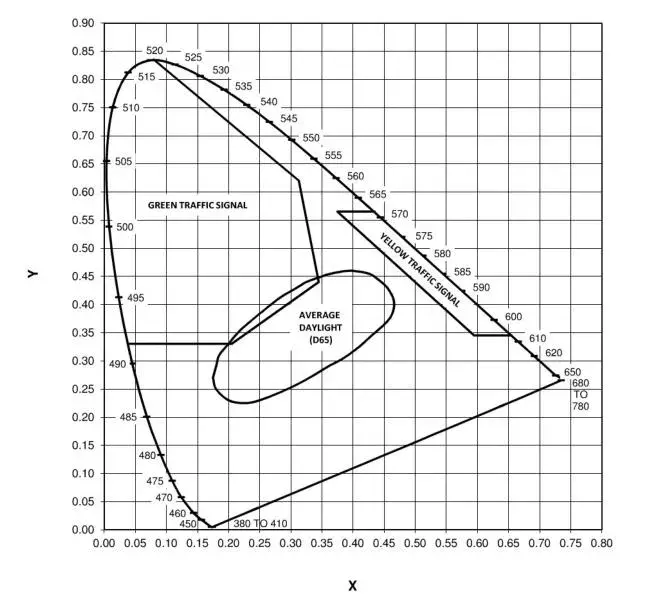
Figure showing the chromaticity coordinate regions for yellow traffic signals, green traffic signals, and average daylight (D65) as specified in section 4.10.2.1
Figure 2: Lens on Tube
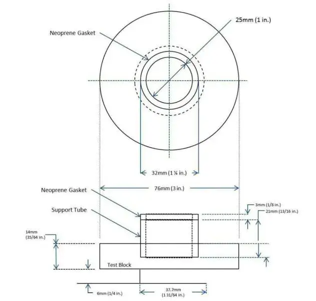
NOTES:
1. Measurements are given in millimeters with corresponding English measurements in parenthesis.
2. The test block is to be inserted in the baseplate described in Figure 3 of this standard.
This test block is applicable to the majority of ophthalmic lenses. However, if any diameter of the edged lens is less than 32 mm (1-1/4 in), a substitute support may be used the outside diameter of which is equal to or less than the smallest diameter of the edged lens. The wall thickness of the neoprene gasket is a nominal 3 mm (1/8 in).
Read More